H Series
Configuration
Screen Setup
1. H Configuration Preparations
1.1. Hardware Connection
This document introduces the hardware interfaces and how to connect and use them.
Interface Introduction
This section introduces common interfaces and cables.
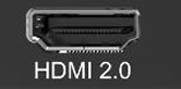
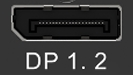
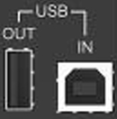
Video interface


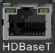
AV over IP
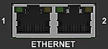
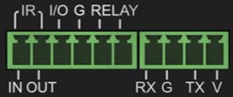
Control interface


Hardware Connections
This section details the physical connection process, including power, video inputs/outputs, and control interfaces.
Preparation
- Confirm all package contents, including the device, power cord, and video cables (e.g., HDMI, DP).
- Gather necessary tools, such as a screwdriver or network cable.
Connection Steps
- Power Connection: Connect the provided power cord to the device's power input and plug it into a power outlet.
- Video Input Connection:
- Connect the HDMI/DP/DVI output from your video source (e.g., a computer, media player) to the processor's input ports using the appropriate cables.
- ❗ Warning: Ensure the input signal resolution and refresh rate are within the device's supported range.
- Video Output Connection:
- Connect the processor's output ports (typically RJ45) to the cabients.
- Control Connection:
- Use a network cable to connect the device's RJ45 control port to your computer's network port for software control.
- System connection reference
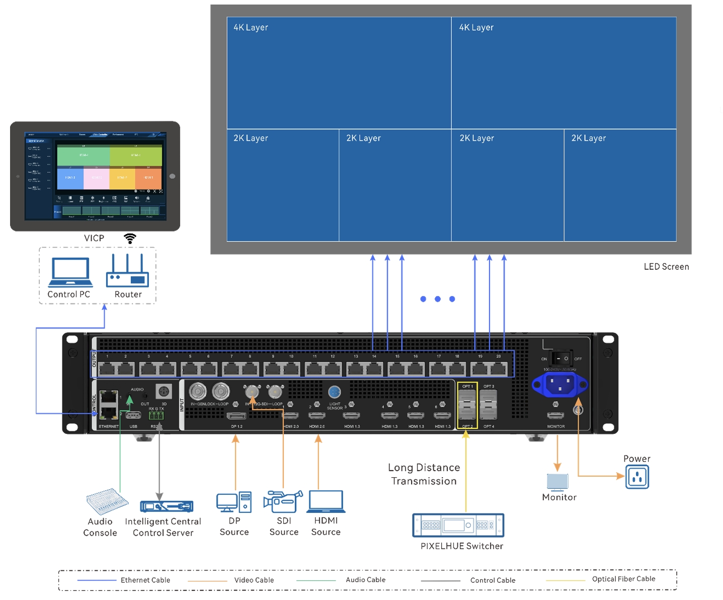
⚠️ Note: Please complete all cable connections before powering on the device to prevent hardware damage from hot-swapping.
1.2. Screen Configuration
[Content to be added.]
1.3. Firmware Upgrade
Firmware Update
The H series supports firmware update through the Web page. Make sure you have downloaded the update package from NovaStar's official website before the update. The system supports the update for the control card, AUX and MVR cards, input cards and output cards. You can select to update a single component or the whole unit.
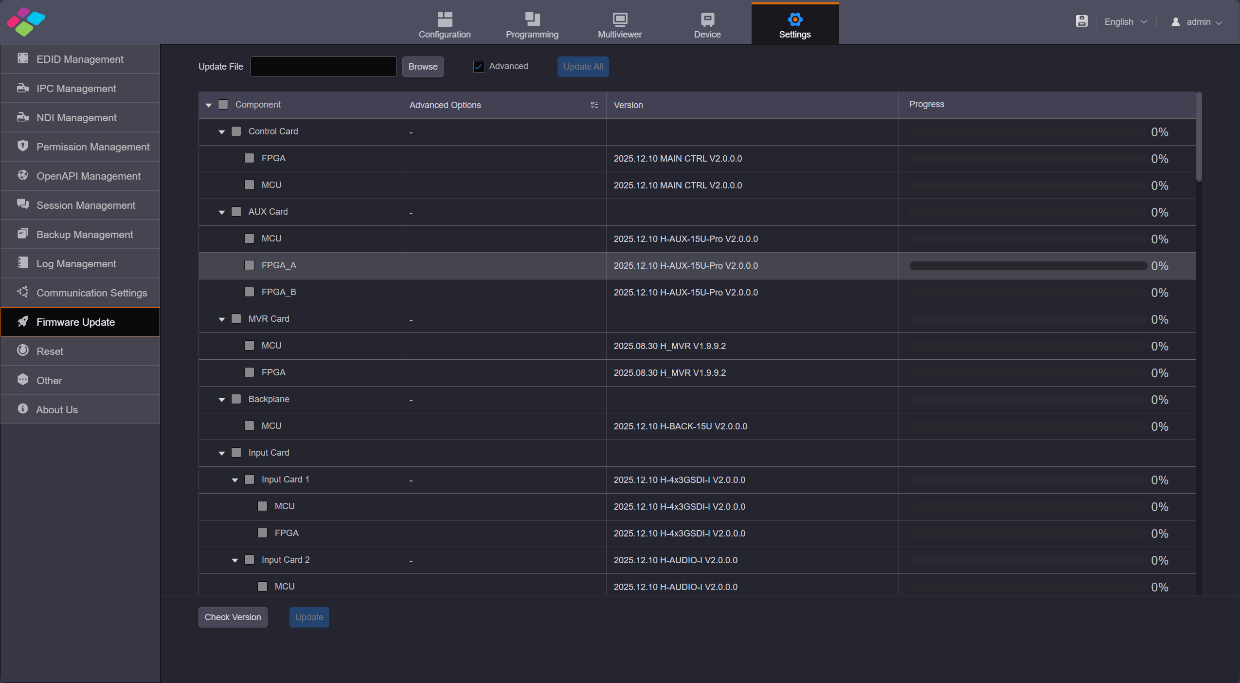
Firmware update
The update procedure is as follows
- Step 1: Firstly, make sure you have downloaded the software package of the component to be updated from NovaStar's official website.
- Step 2: Settings, Click Firmware Update on the left to enter the update page.
- Step 3: Click Browse to load the update package with.zip formate.
- Step 4: Click Update All to update all components automatically, the device will restart when it finishes. When you select Advance Update, you can choose to upgrade a specific sub-card individually.
Notes
- To ensure a smooth update progress and complete data compatibility, please follow the specified intermediate version sequence for step-by-step update when updating from V1.0.0.0 to V2.0.0.0. Any intermediate version should not be skipped. The mandatory update sequence is as follows: 1.0.0.0 > 1.3.2.0> 1.6.4.0 >1.9.4.0 >1.9.9.2 >2.0.0.0
1.4. Hweb-Input&Output
H Series Input and Output EDID Settings
Click the Settings on the top, the first option is EDID Management.
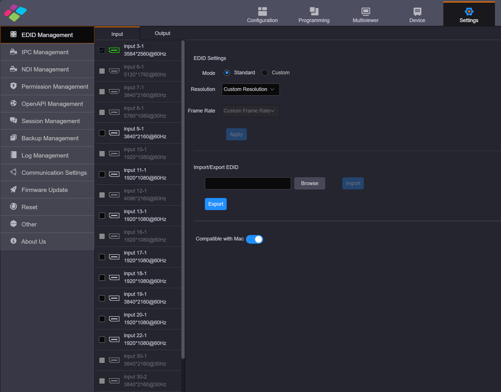
Input Settings
Input Settings
You can set the input EDID through the following three ways.
- Standard Mode Select an input resolution from the drop-down list of Standard Resolution and frame rate,and Apply.
- Custom Mode Set the width, height and frame rate for the input connectors and Apply.
- Import/Export EDID Click Browse select the desired EDID configuration file, and import it for quick configuration. Click Export allows you to export the EDID file of the current interface.
- Compatible with Mac To improve the accessexperience of Apple devices and enhance the native compatibility ofinput cards with Apple devices, the HDBASET, HDMI, and DP connectors now support the intelligent EDID management. This directly addresses the mismatch between the output resolution of Apple devices and the EDID requirements of the video wall splicer. Once enabled, Mac devices can push EDID resolutions that meet the input connectorsrequirements to the video wall splicer, fundamentally resolving display compatibility issues between Apple devices and the video wallsplicer.
Output Settings
Video Output Card EDID Settings.
- The EDID settings section should be consistent with the EDID settings in the input section.
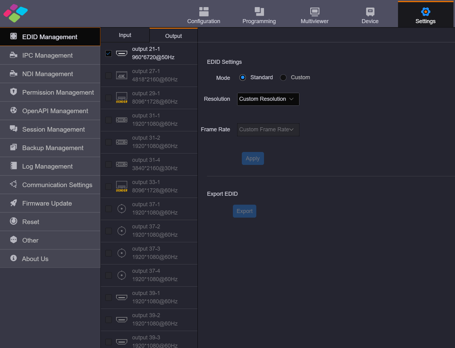
Video Output Card EDID Settings
Sending card resolution settings.
- Generally, when configuring a LED screen, the output resolution of a single LED sending output card is set to the maximum width and height of the screen it loaded.
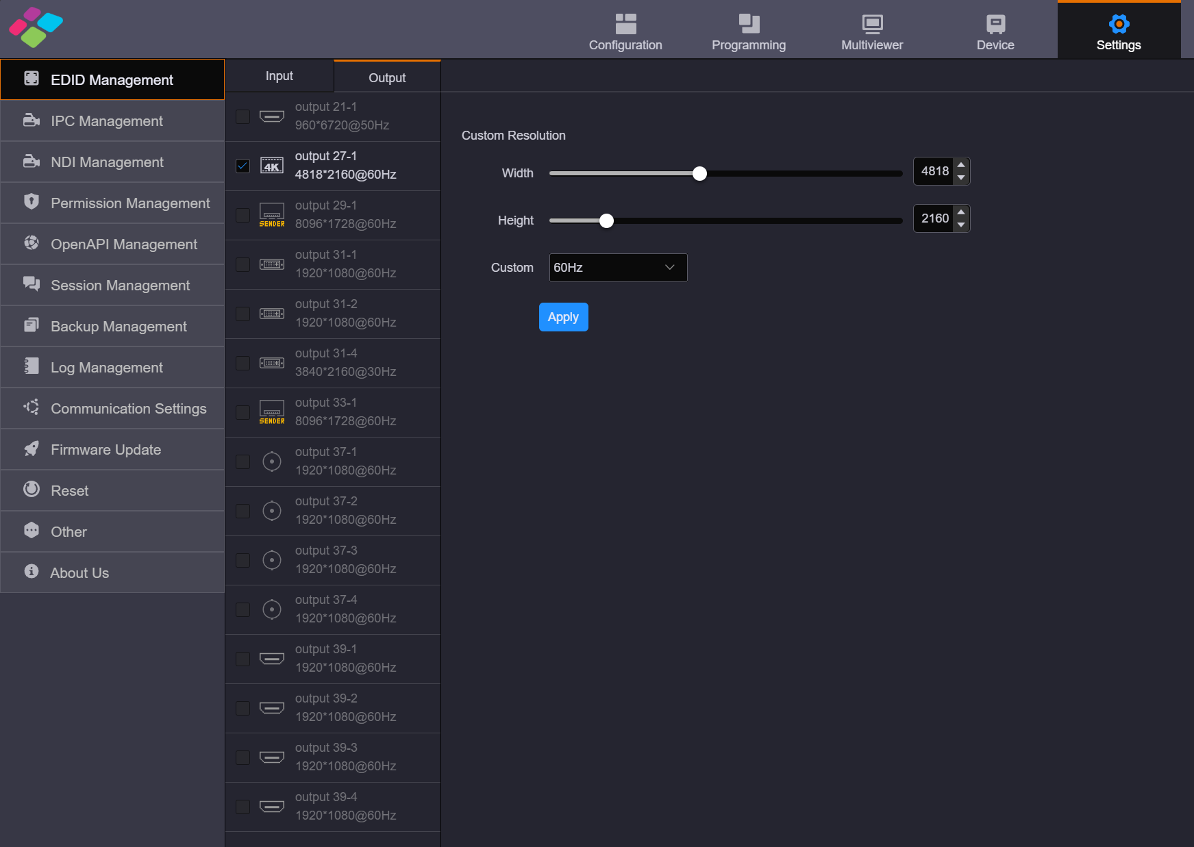
Output Resolution Settings
1.5. Hweb-Configuration
Log in to H web
- Step1: Nsure the H-series device is connected to your control computer via a direct Ethernet cable or through a switch.
- Step2: Modify the IP addresses of both the computer and the device to ensure they are on the same subnet. For example, if the device's IP address is 192.168.0.10, the control computer's IP address should be 192.168.0.X (where X cannot be 10).
- Step3: Open a browser, enter the IP address of the H-series device, and you will see the following login page. The default username and password are both "admin".
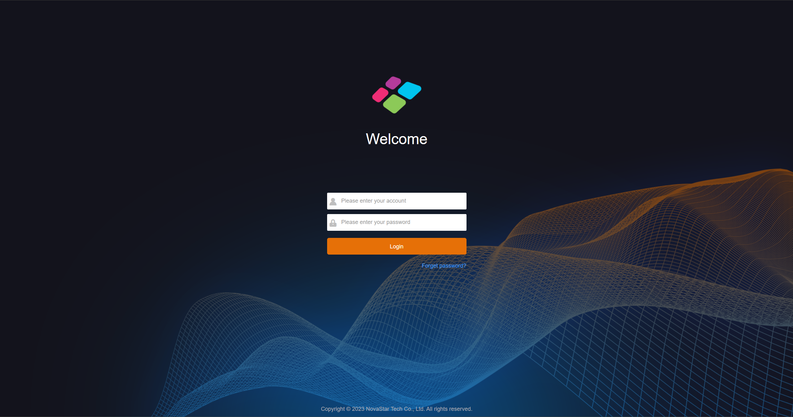
H Series Login Interface
H Web Screen Configuration
After logging in, you will enter the H-Series web editing interface.
H Web Editing Interface
Configure LED screen
- The H series as a Splicer, allows multiple output sending cards to be tiled together, enabling the loading of larger screens or the management of multiple screens. Based on the screen structure and wiring method of the current device, configure the screen and associate it with the output sending cards.
- When using the network port output sending card, the web control interface does not display the actual network output port. One network port sending card uses one 4K virtual output interface for display.
- ⚠️ Note:
- The H_16xRJ45+2xfiber sending card and H_20xRJ45 sending card can be configured on the same screen whenthey have the same frame rate.
- The fiber sending card cannot be used together with the H_20xRJ45 sending card or H_16xRJ45+2xfiber sending card to load the same screen.
- The H_4xfiber sending card (enhanced) cannot be used together with the H_4xfiber sending card to load the same screen.
H Web Operation Steps
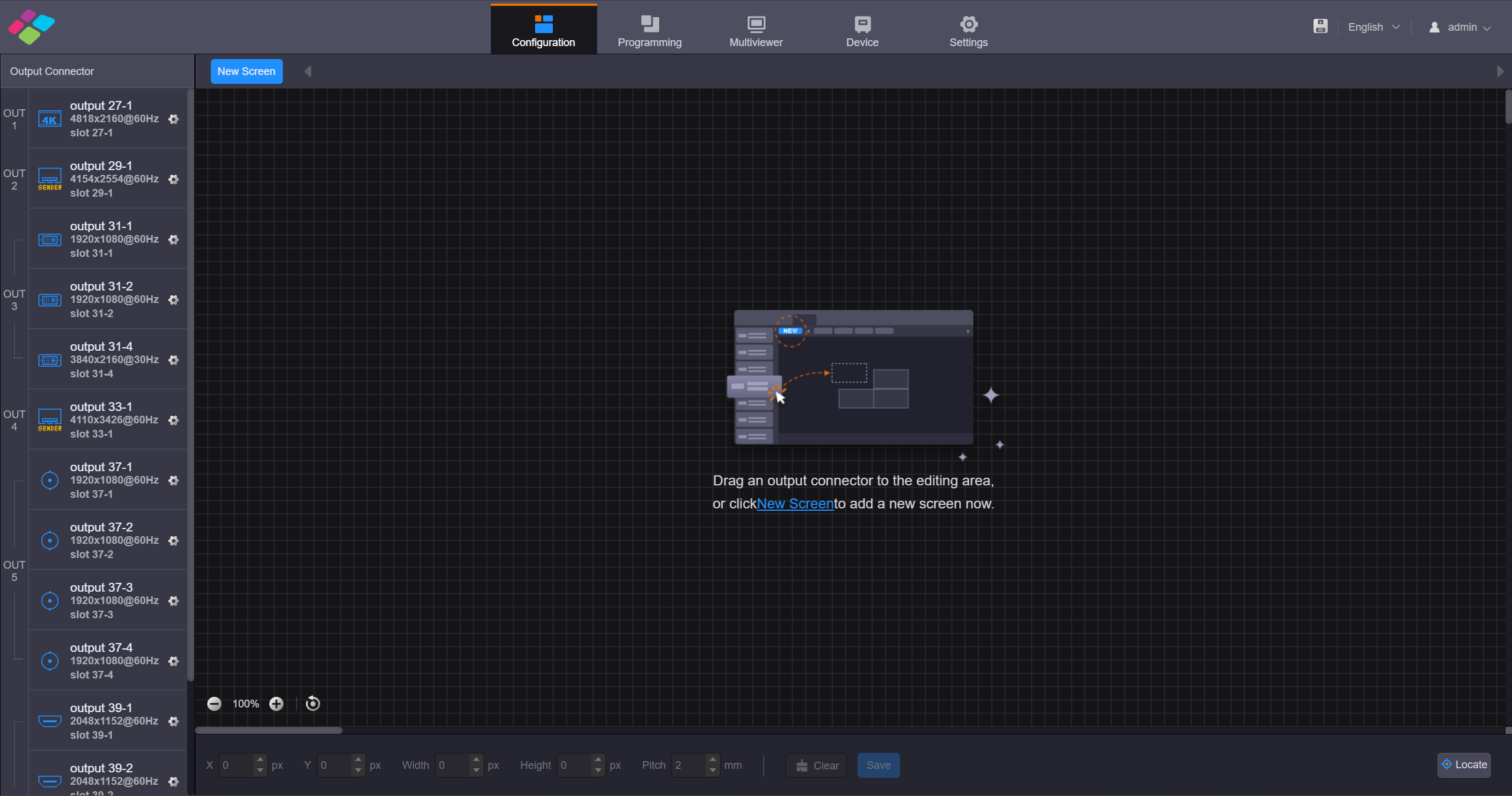
- Step 1: Select "Screen Configuration" to enter the screen configuration interface.
- Step 2: Click "New Screen" to enter the "New Screen" editing interface.
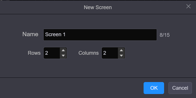
Create Screen
- Step 3: Configure the number of rows and columns for the output interface splicing based on the current screen structure and the relationship with the output interface.
- Step 4: Select the output card that loads the screen, drag the sending card to the editing area of the screen, and complete the screen editing.
- ⚠️ Note:
- When you use the H_16xRJ45+2xfiber sending card or H_20xRJ45 sending card, it is recommended you go to Settings> EDID Management> Outputto set the output resolution and frame rate first.
- When you use the H_4xfiber sending card, go tothe Devicepage to configure the connector working mode first, and then go to Settings> EDID Management> Outputto set the output resolution and frame rate
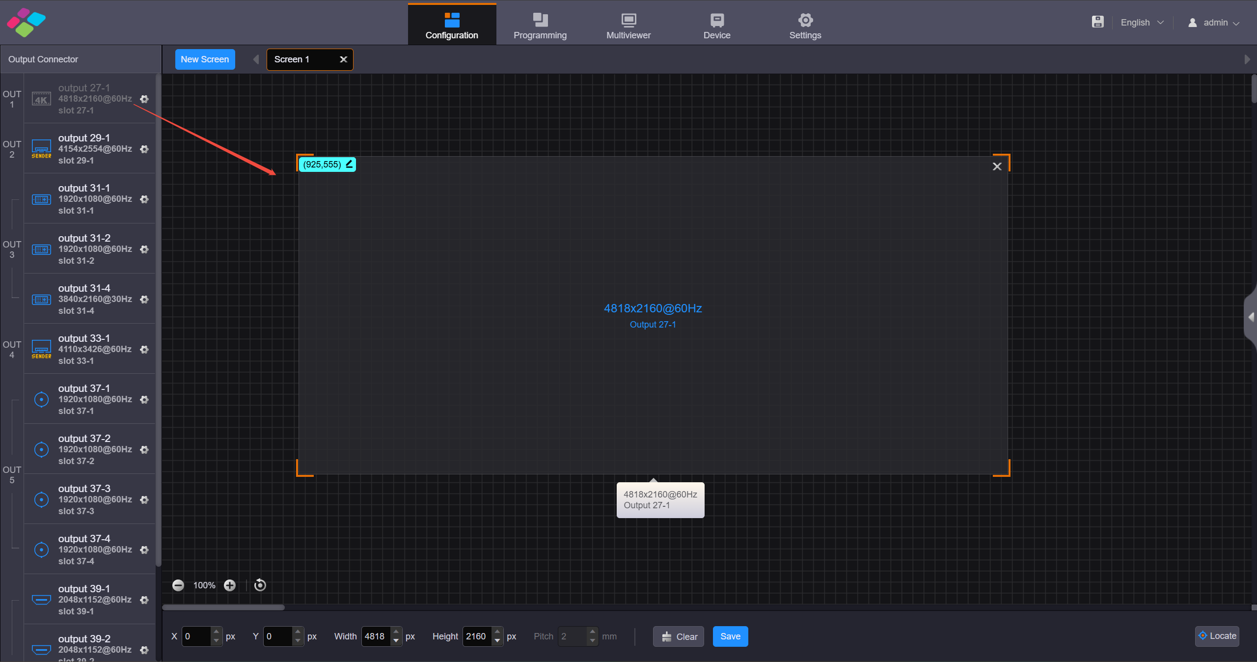
LED Screen Configuration
- Step 5: Click "Save" to complete screen editing.
NovaLCT Screen Configuration Steps
When the H_16xRJ45+2xfiber sending card, H_20xRJ45 sending card or H_4xfiber sending cardis used, you must configure the screen in NovaLCT
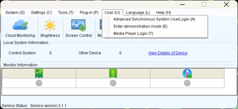
- Step 1: Go to User> Advanced Synchronous System User Login. Enter the password and click Login. The default password is "admin".
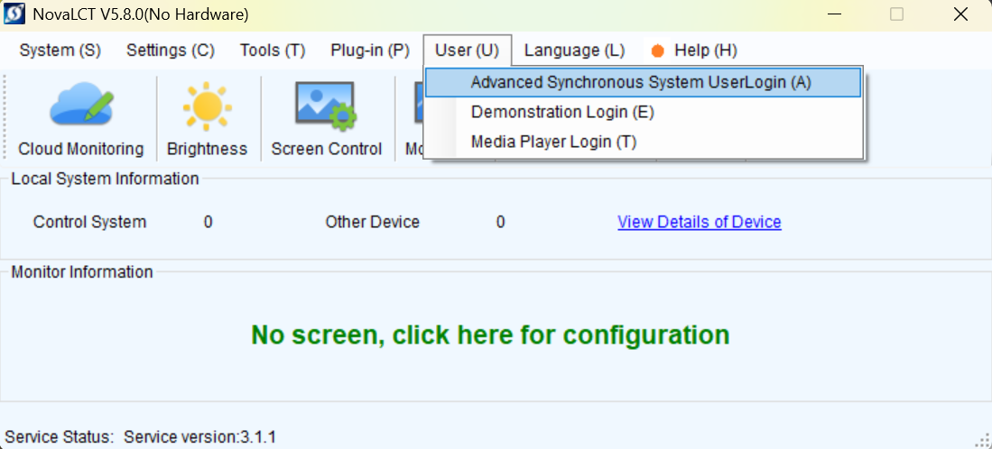
Log in to LCT
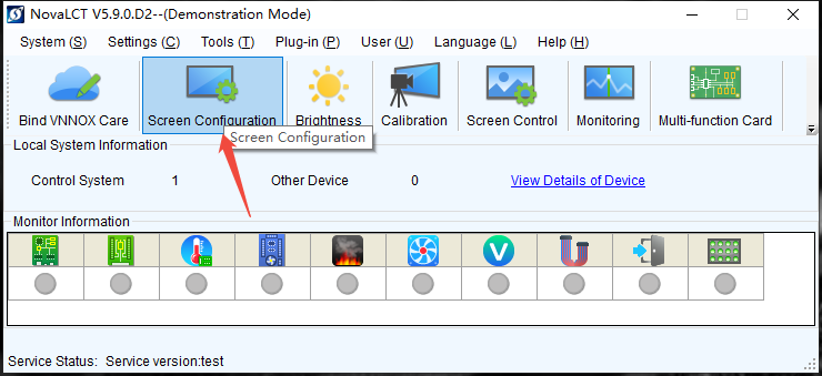
- Step 2: Click on "Screen Configuration" to open the display configuration interface.
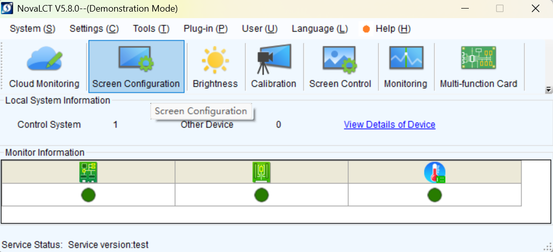
Screen Configuration
- Step 3: Select a communication port and click Next.
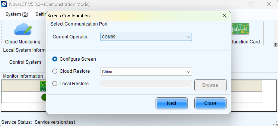
Select communication port
- Step 4: Select the Screen Connection tab to show the screen configuration settings. Refer to the NovaLCT screen configuration for the remaining setup steps.
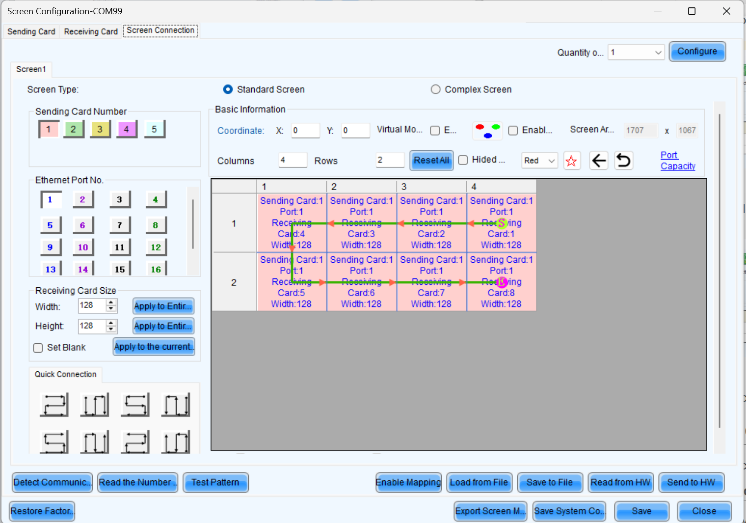
Screen Configuration
Configure LCD screen
- Step 1: Select Configuration to enter the screen configuration page.
- Step 2: Click New Screen at the top to open the New Screen window.
Create Screen
- Step 3: Select the output card that loads the LCD screen, drag the output card to the editing area of the LED screen, and complete the screen editing.
- Step 4: Click "Save" to complete screen editing.
Introduction to Programming
Once the screen configuration is complete, you can click the "Programming" interface to set the layer properties.
Add Layers
- Step 1: Click Programming to enter the layer editing page.
- Step 2: On top of the Programming page, select the screen that you will operate.
- Step 3: Click an input in the Input Signal area on the left and drag it to the editing area to add a layer.
Adjust Layers
Click the layer and you can perform the following operations.
Adjust the layer size
- Quick adjustment: Click the small square on the layer edge, and drag the square when the cursor turns to a double-sided arrow to quickly adjust the layer size.
- Precise adjustment: Enter specific numbers in the Wand H text boxes below the layer editing area to precisely adjust the layer size
Layer position adjustment
- Quick Adjustment: Place the mouse inside the layer, hold down the left mouse button and drag to quickly adjust the layer's position.
- Precise Adjustment: Enter specific numbers in the text boxes after "X" and "Y" below the layer to precisely adjust the layer's position, based on the top-left corner of the layer.
Layer Capacity Adjustment
- In the "Devices" interface, click on the input card of the input source you want to adjust, and modify the interface capacity in the "Capacity" section of the input card properties on the right.
Save Preset
After completing the layer settings, you can save the edited content as a "preset," allowing multiple presets to cover different usage scenarios.
- Step 1: On the Programming page, click Save Preset below the layer editing area to open the preset saving window.
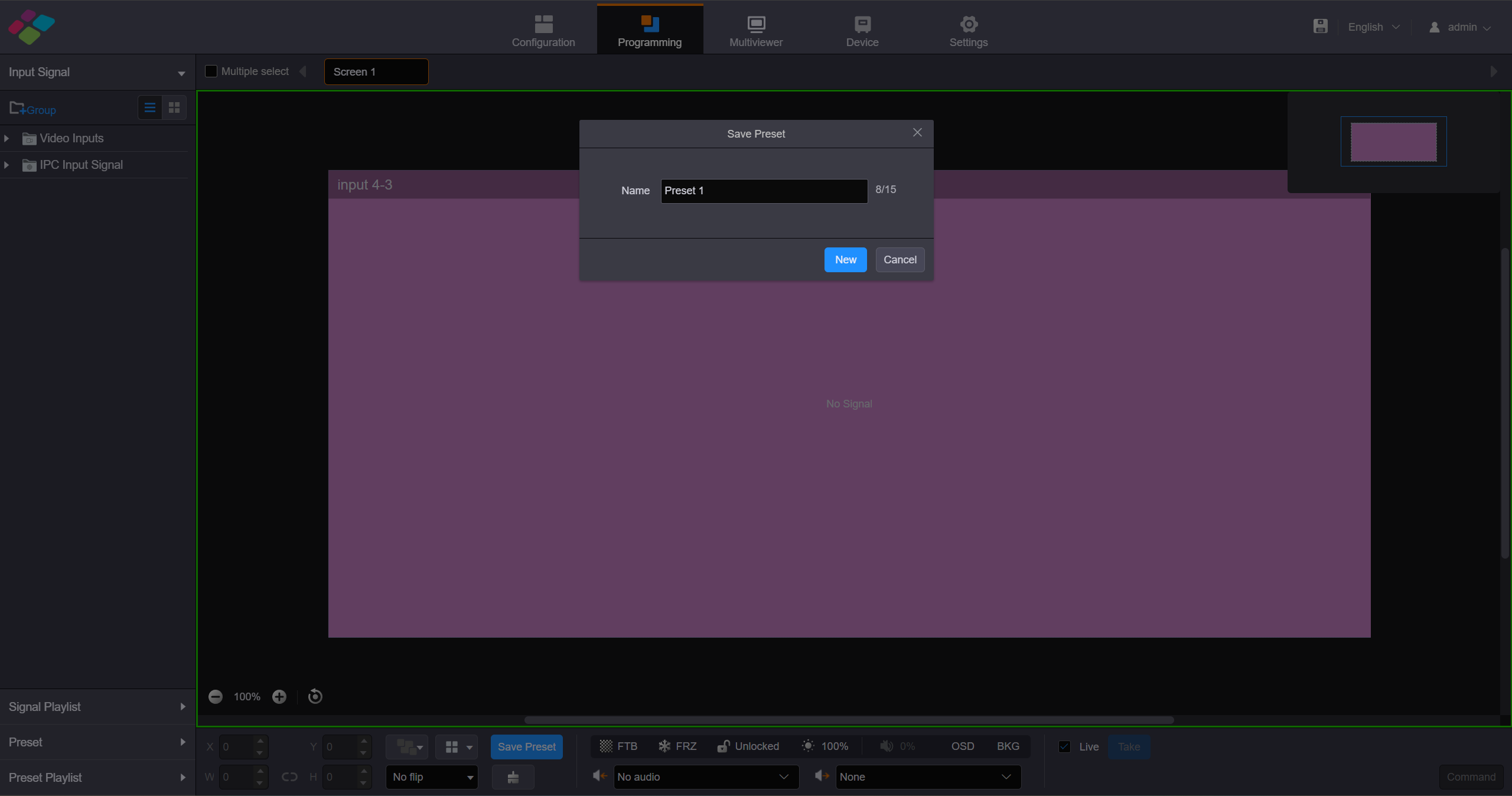
Save Preset
- Fill in the scene name according to actual needs.
- Click "Save" to complete the scene saving.
- Click "Preset" on the left to open the scene list and manually switch between different scenes.
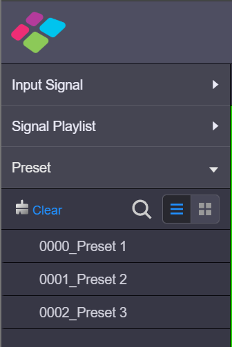
Preset switching
- The preset playback function allows you to play the presets automatically based on the set playback sequence and single preset playback duration. After the settings, the system will play the presets automatically with no manual operations required. On the Programming page, click Preset Playlist on the left to enter the preset playlistsettings page.
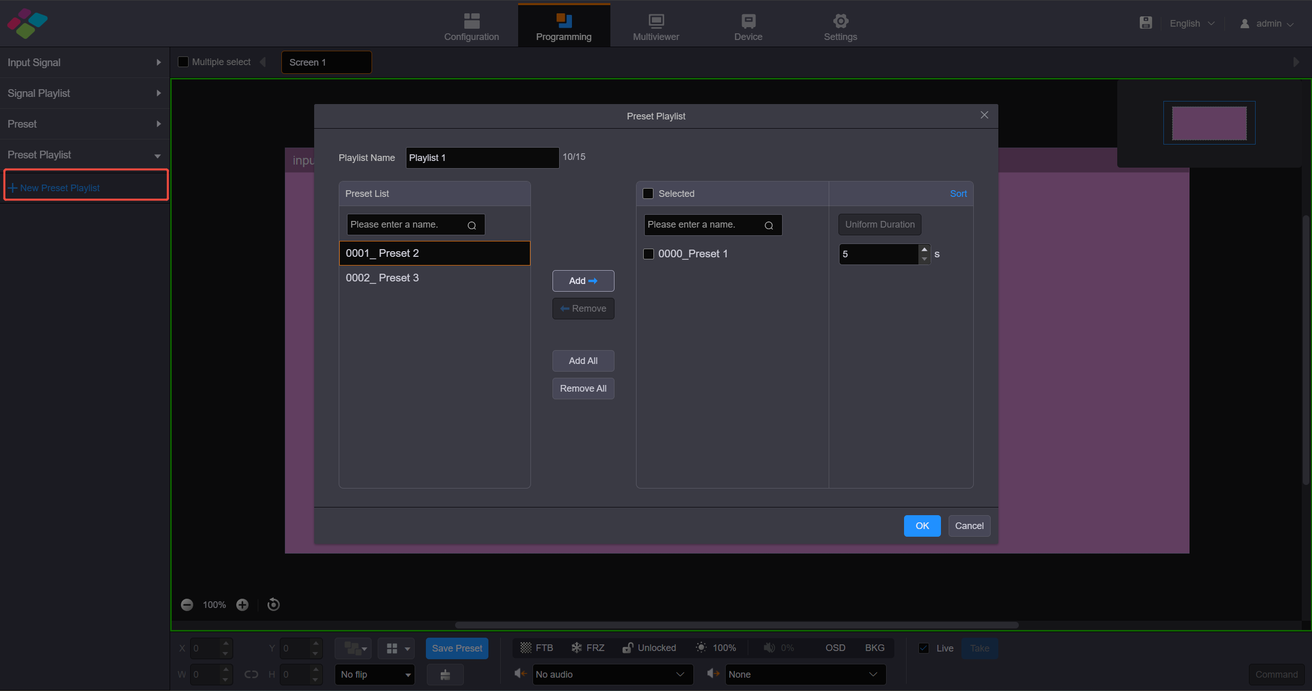
Set Preset Playlists
Add BKG
- On the Programming page, click BKG below the layer editing area to expand the BKG settings pane.
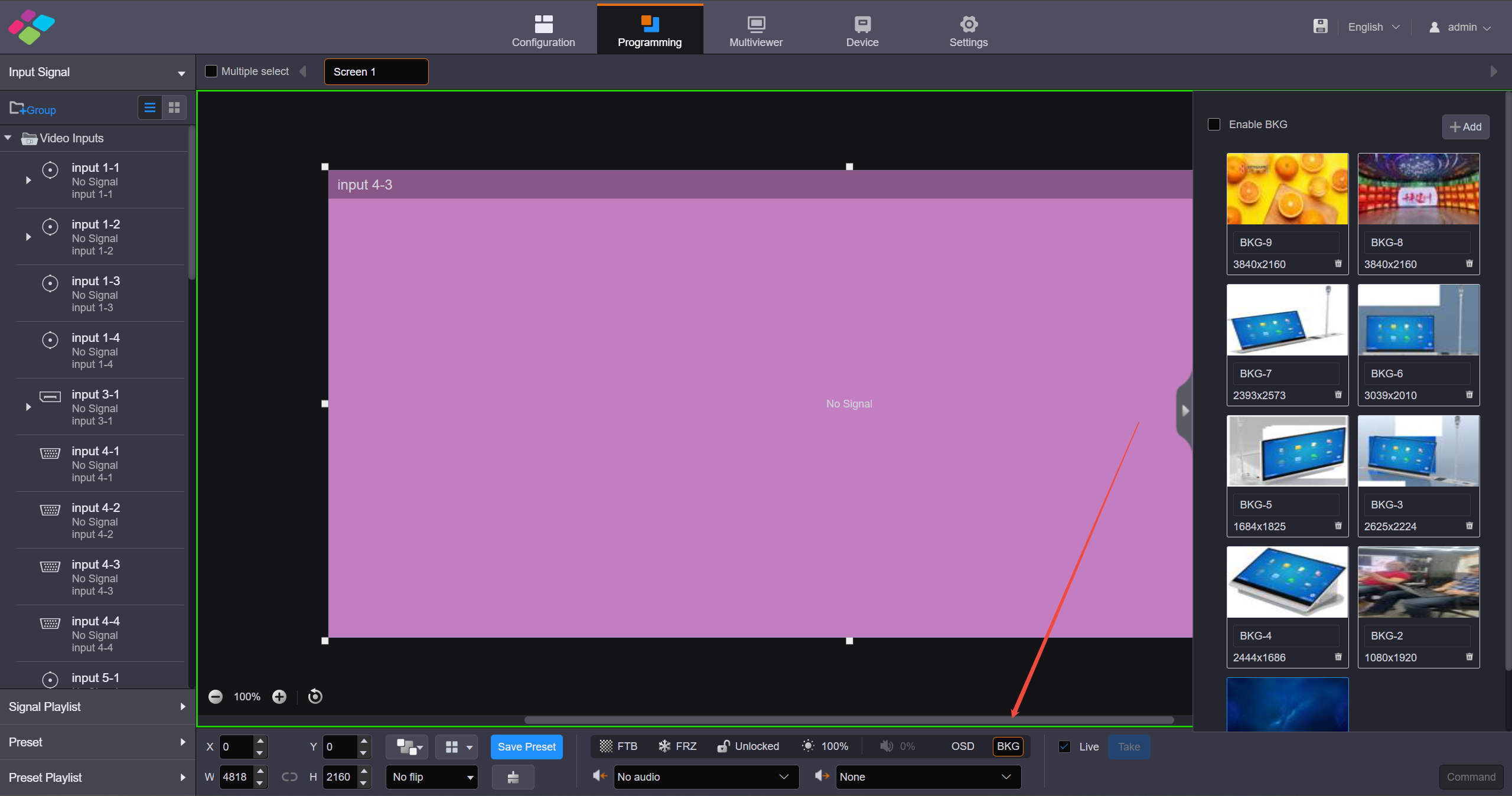
Add BKG
- Click Add to openthe window where you can select and add a BKG file.
- Select the desired file and click Open to add it to the BKG list.
Add OSD
- The H series supports various OSD options, including static text OSD, dynamic text OSD, weather OSD, clock OSD and image OSD. OSD is displayed at the top level and its priority cannot be adjusted.
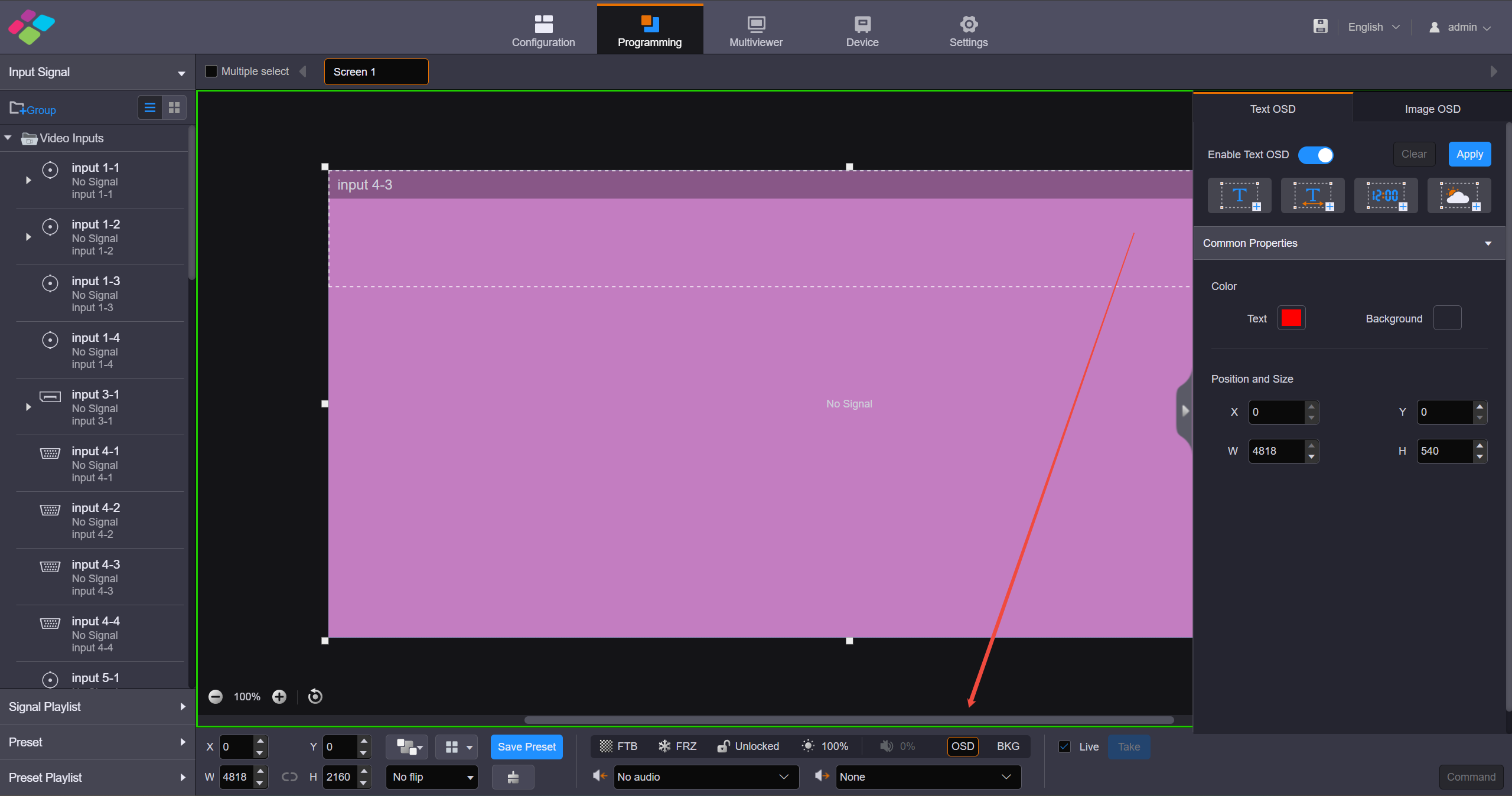
Add OSD
2. Screen Configuration
2.1. Cabinet Configuration
RCFGX, NCP files
How to load the RCFGX file
What is RCFGX file:
An.rcfgx file is a Receiving Card Configuration file used primarily by NovaStar LED display systems. It acts as a configuration profile, containing essential parameters like resolution, scan mode, pixel mapping, and refresh rate for LED panels.
Where can you get the file:
The RCFGX file is provided as a standard working file with the cabinet upon shipment. For additional files, you can contact the LED screen manufacturer's relevant staff to obtain them.
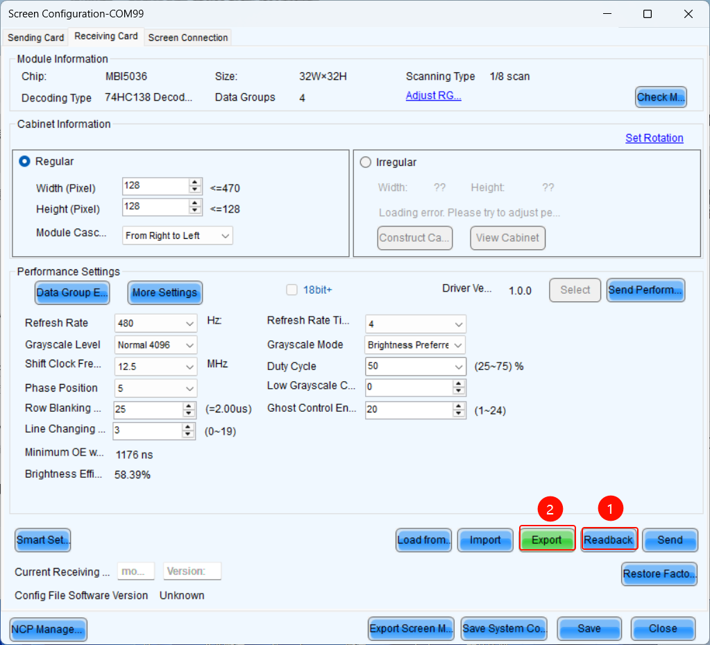
1. Save the RCFGX file to your local computer:
- When you have a cabinet that is functioning properly, you can read back its parameters in LCT and save the RCFGX file to your local computer.
2. Load RCFGX file:
- After that, you can import the exported RCFGX file into the new, unconfigured cabinet.
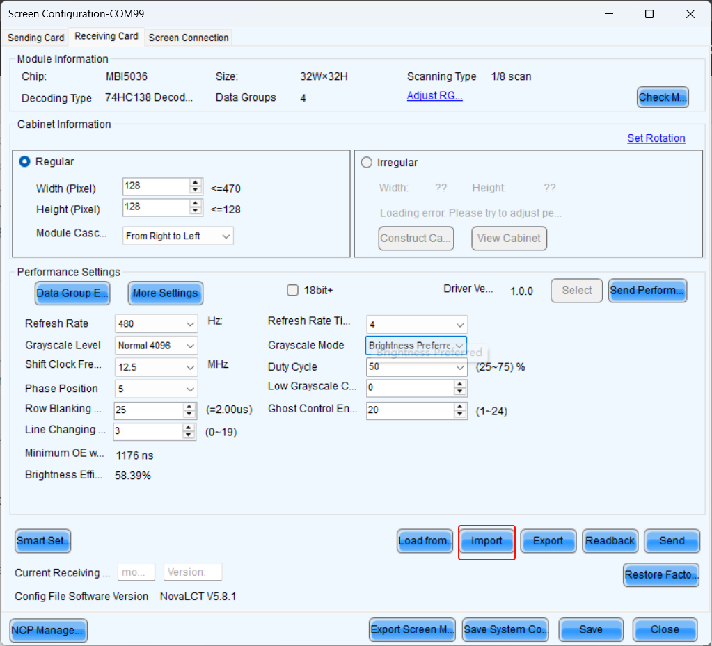
click import
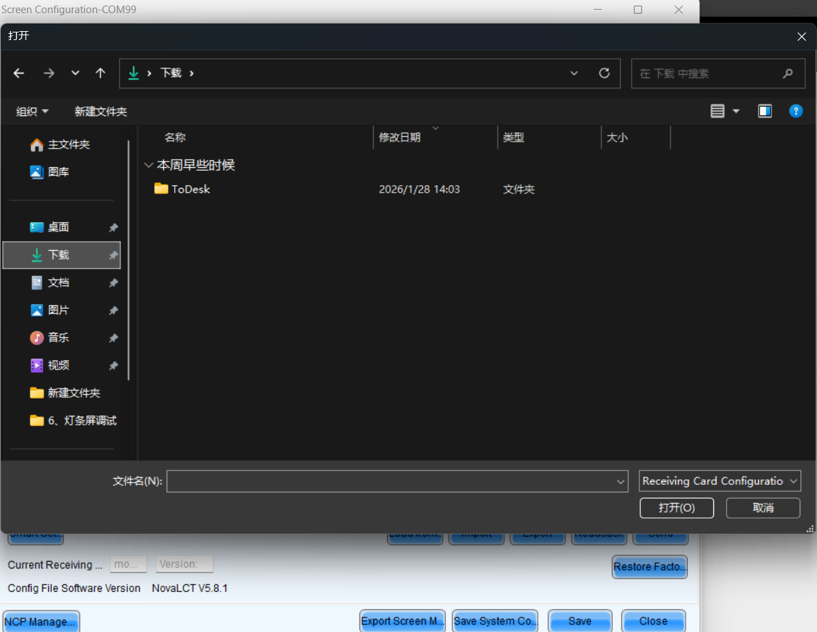
choose the right file
How to send the RCFGX file
- After importing a new RCFGX file, the parameters will not be sent directly to the receiving card. You need to click the send button.
Before saving to hardware, ensure the display is functioning perfectly.
- After successfully sending the parameters to the receiving card, click Save to store the parameters in the hardware, ensuring data remains intact after power cycling.
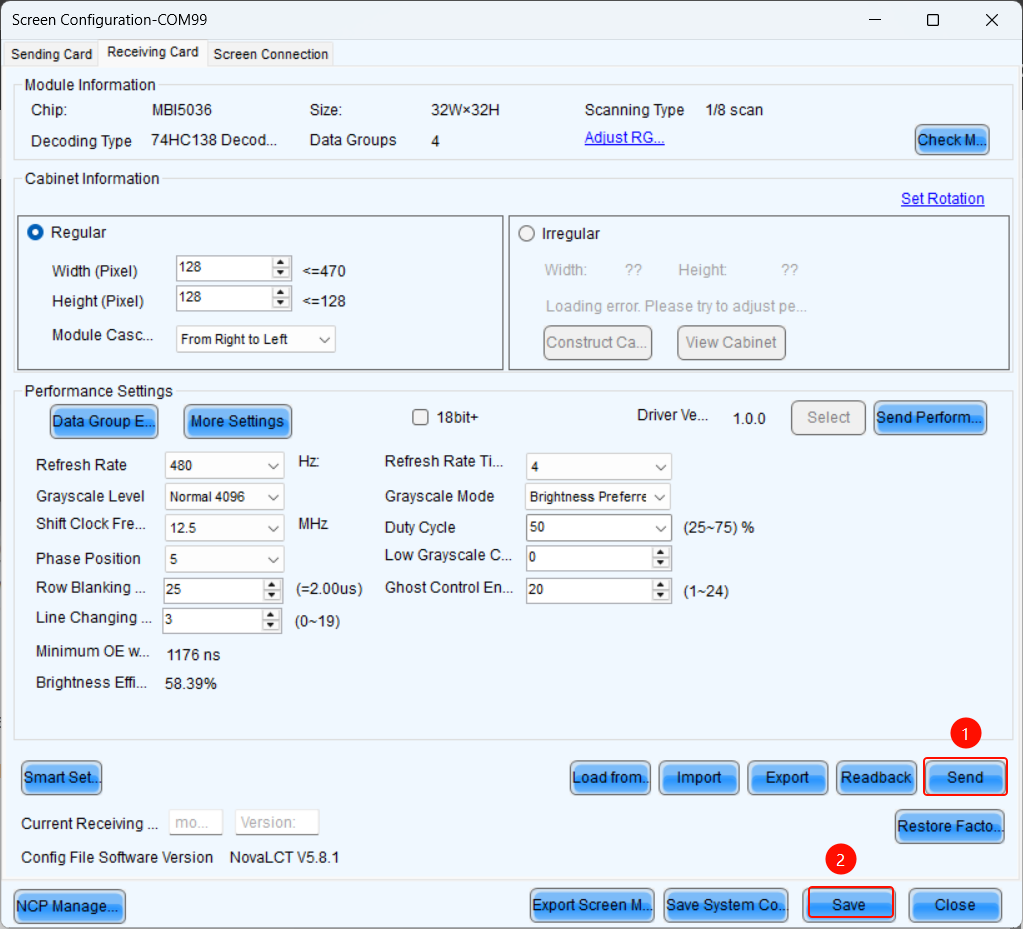
send and save to HW
How to send the NCP file
1. What is NCP file:
You can click the link below to check the information about the NCP file.
https://coex.wiki/en/Intro&Info/NCP-File
2. How to send NCP file with NovaLCT:
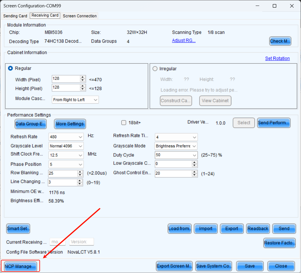
- Step 1 On the Screen Configuration page, click the Receiving Card tab for NCP Management.
If the Receiving Card tab defaults to the.rcfgx/.rcfg configuration interface, click NCP Management to enter the NCP management interface.
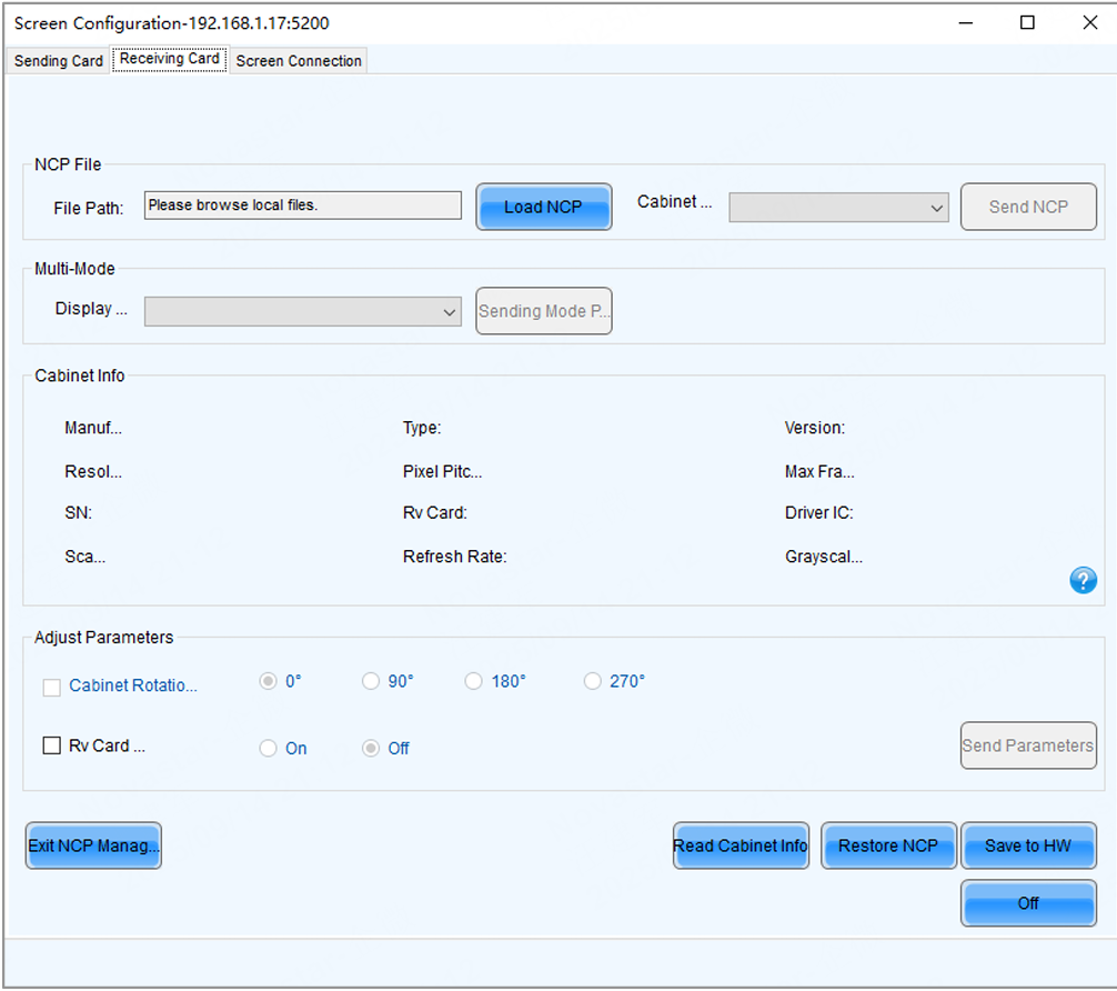
- Step 2 Click Load NCP.
- Step 3 On the pop-up window, choose an.ncp file, and click Open.
- Step 4 Send the cabinet file and display mode parameters.
Select a cabinet file from the drop-down list and then click Send NCP.
Select a display mode from the drop-down list and then click Send Mode Parameters.
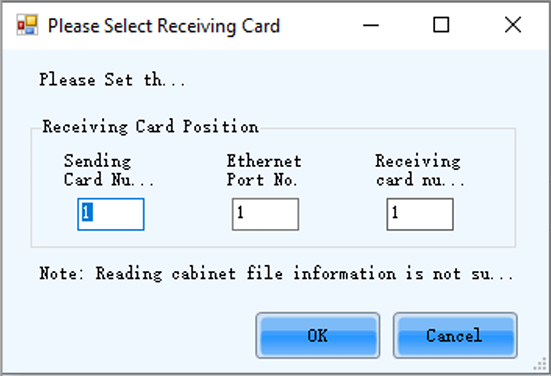
- Step 5 On the pop-up window, select the target receiving cards and click Send.
All Receiving Card: Send the receiving card configuration information to all the receiving cards loaded by the current sending card. If you select Reset the Starting Coordinate of Receiving Card, the starting coordinates of all the receiving cards will be reset to (0, 0). As a result, all the receiving cards display the top-left image of the input source.
Specified Receiving Card: Send the receiving card configuration information to the specified cards by sending card, by topology, or by physical address.
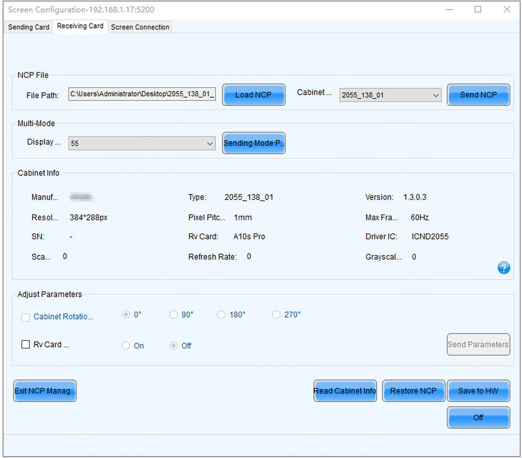
- Step 6 Click Save to HW.
- Step 7 Do the following as required.
Read cabinet information:
Click Read Cabinet Info, set the receiving card address on the pop-up window, and then click OK.
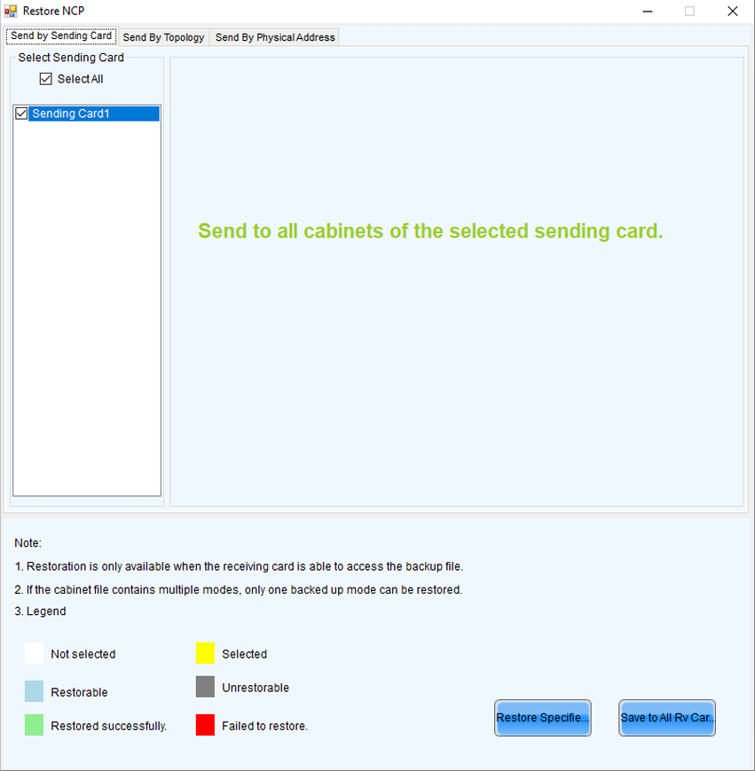
- Restore NCP
a. Click Restore NCP.
b. On the pop-up window, select the receiving cards you want to restore.
c. On the Send by Topology tab, you can click Check Backup Files to check if there is a backup file in the receiving card factory area.
d. Click Restore Specified Rv Cards to restore the backup file in the factory area to DDR.
e. Click Save to All Rv Cards.
- Set cabinet rotation
Select Cabinet Rotation, set the rotation angle, and then click Send Parameters.
- Set receiving card indicator
Select Rv Card Indicator, choose between Enable or Disable, and then click Send Parameters.
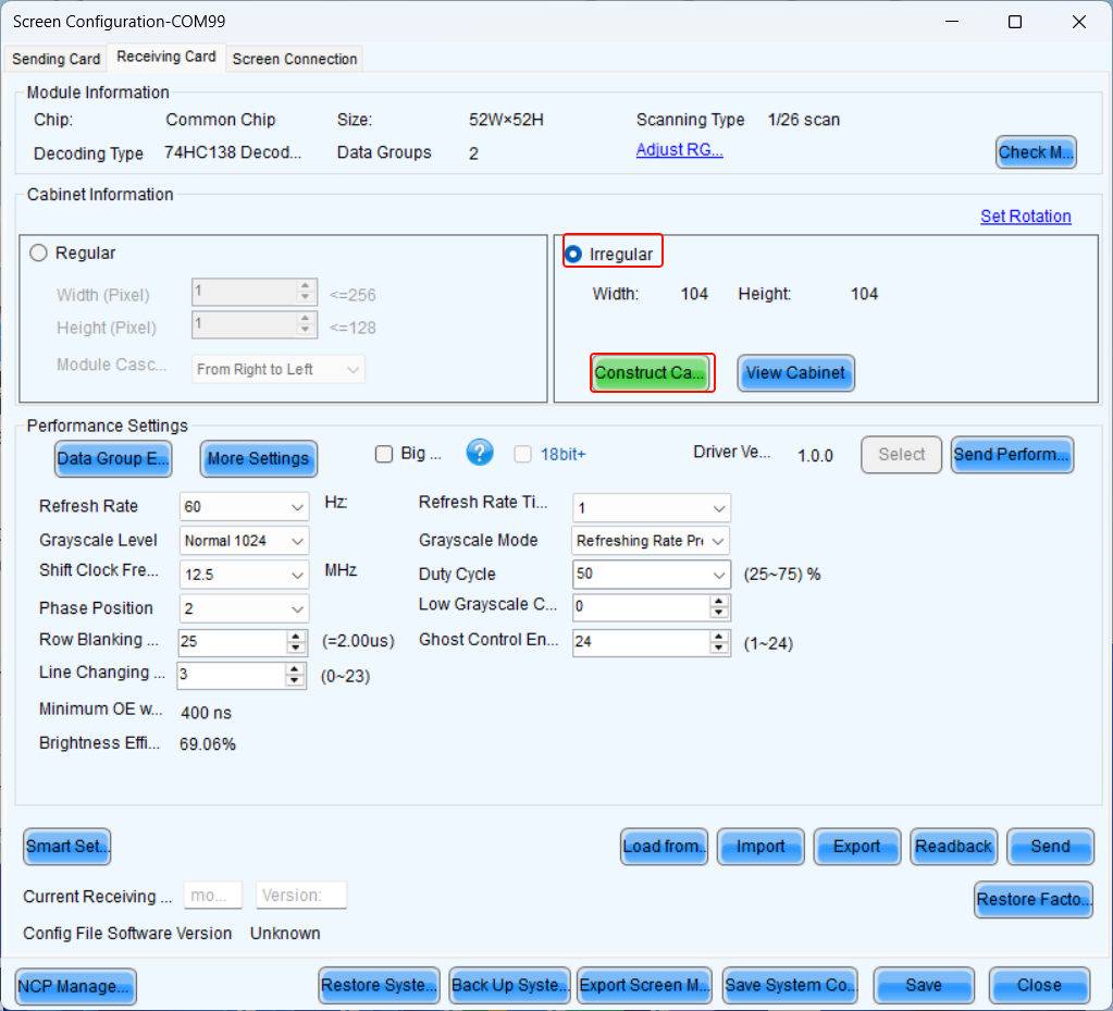
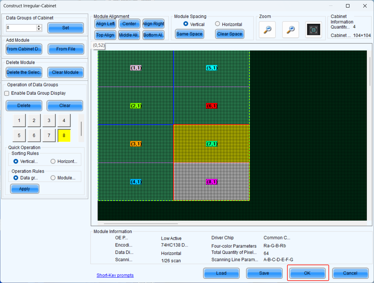
Set Irregular Cabinet
What is the Irregular Cabinet:
If a cabinet is rectangle and the specifications of all the modules are the same, the cabinet is a regular cabinet, otherwise it is an irregular cabinet. For an irregular cabinet, the configuration file must be used to construct the cabinet.
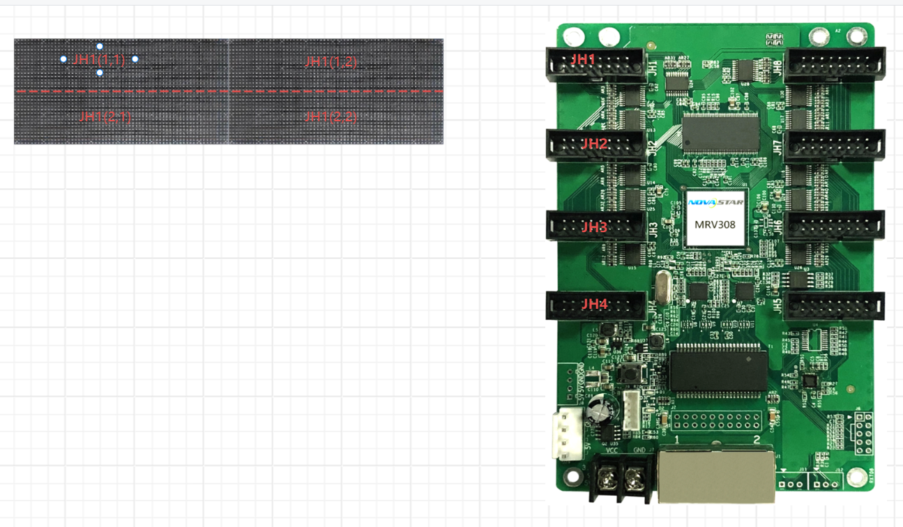
- Data Group
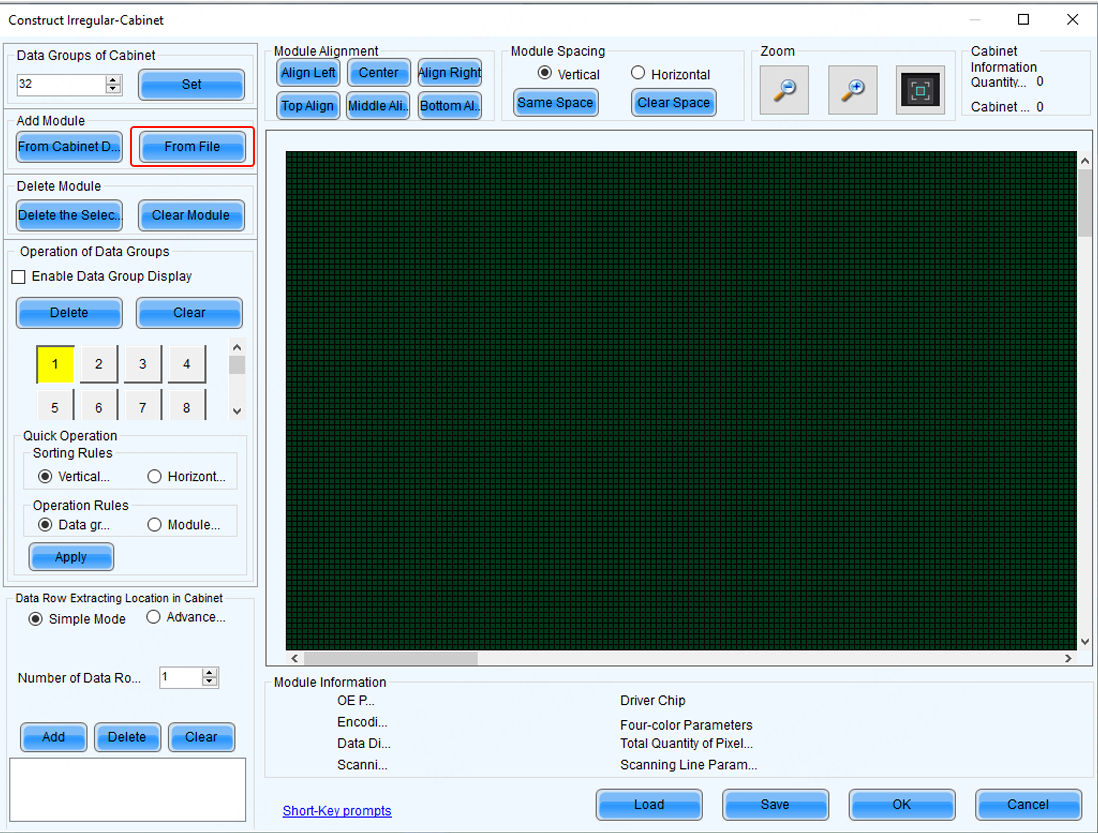
Taking the JH75 port as an example, each JH75 has two data groups. When constructing an irregular cabinet (as shown in the figure), each module has two data groups: the JH1 port data groups are 1 and 2, the JH2 port data groups are 3 and 4, and so on.
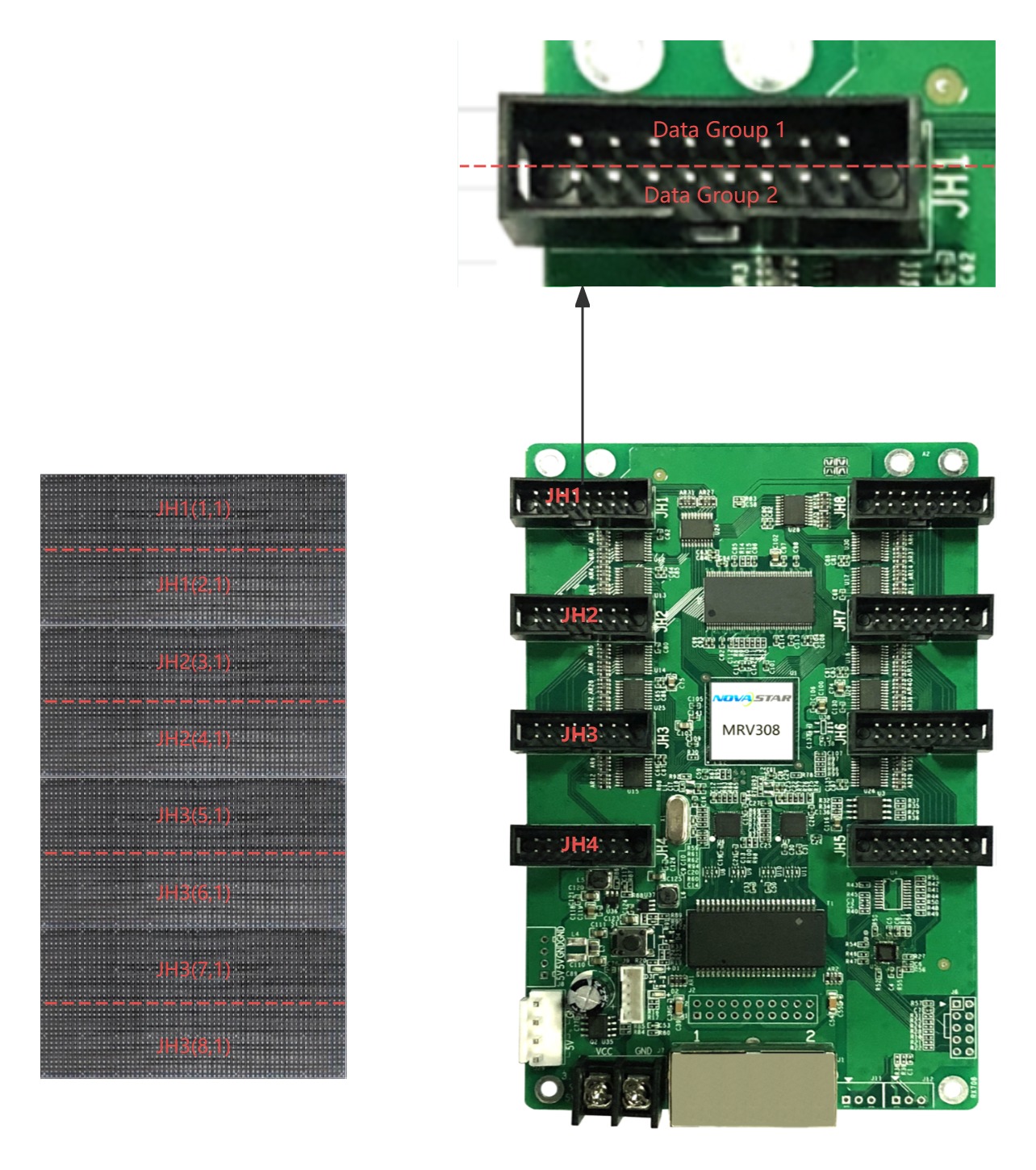
When modules are cascaded, the data group numbers increase (as shown in the figure). For JH1, the first data group consists of (1,1) and (1,2).
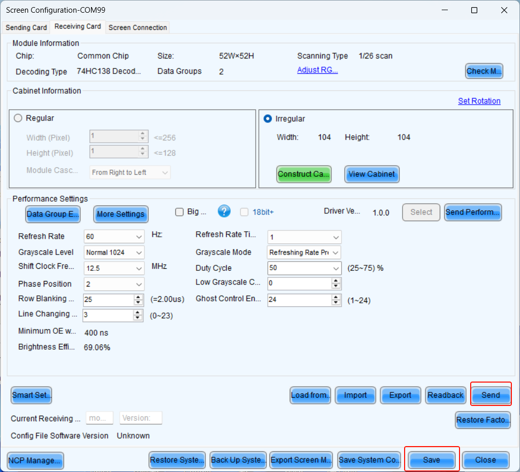
2. Save module file:
Readback the module data, then save the module file locally.
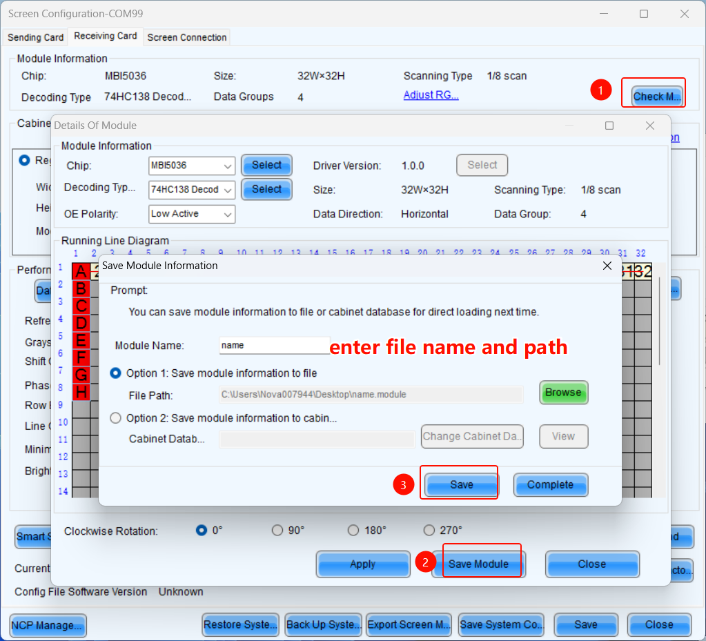
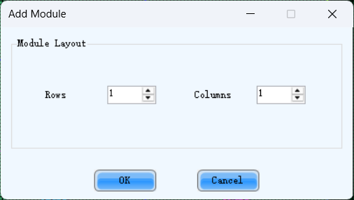
3. Set Irregular Cabinet:
Enter the number of rows and columns as shown in the image, then proceed with the settings.
2.2. Screen Connection
Overview
This document provides a comprehensive guide for the installation, configuration, and operation of the NovaLCT screen connection part.
- Key Features: Use NovaLCT to configure standard and complex screen connections.
Software Configuration and Operation Guide
User login
- When the device is from the MCTRL, VX, VX Pro, H, MEE, KT series, select "Advanced Synchronous System User Login," with the default password set as "admin."
- When the device is from the TB, TU, or JT series, first connect to the AP Wi-Fi named by device's SN. The default password is either "12345678" or "SN2008@+", then select "Media Player Login." The default account is "admin," and the default password is either "123456" or "SN2008@+".
Screen connection
Standard Screen Connection
- Click "Screen configuration," then select the corresponding device IP or COM port, and click Next to enter the "Screen Connection" configuration interface.
- Take a 3x3 LED screen as an example, the resolution of a single cabinet is 480x270.As shown in the figure below.

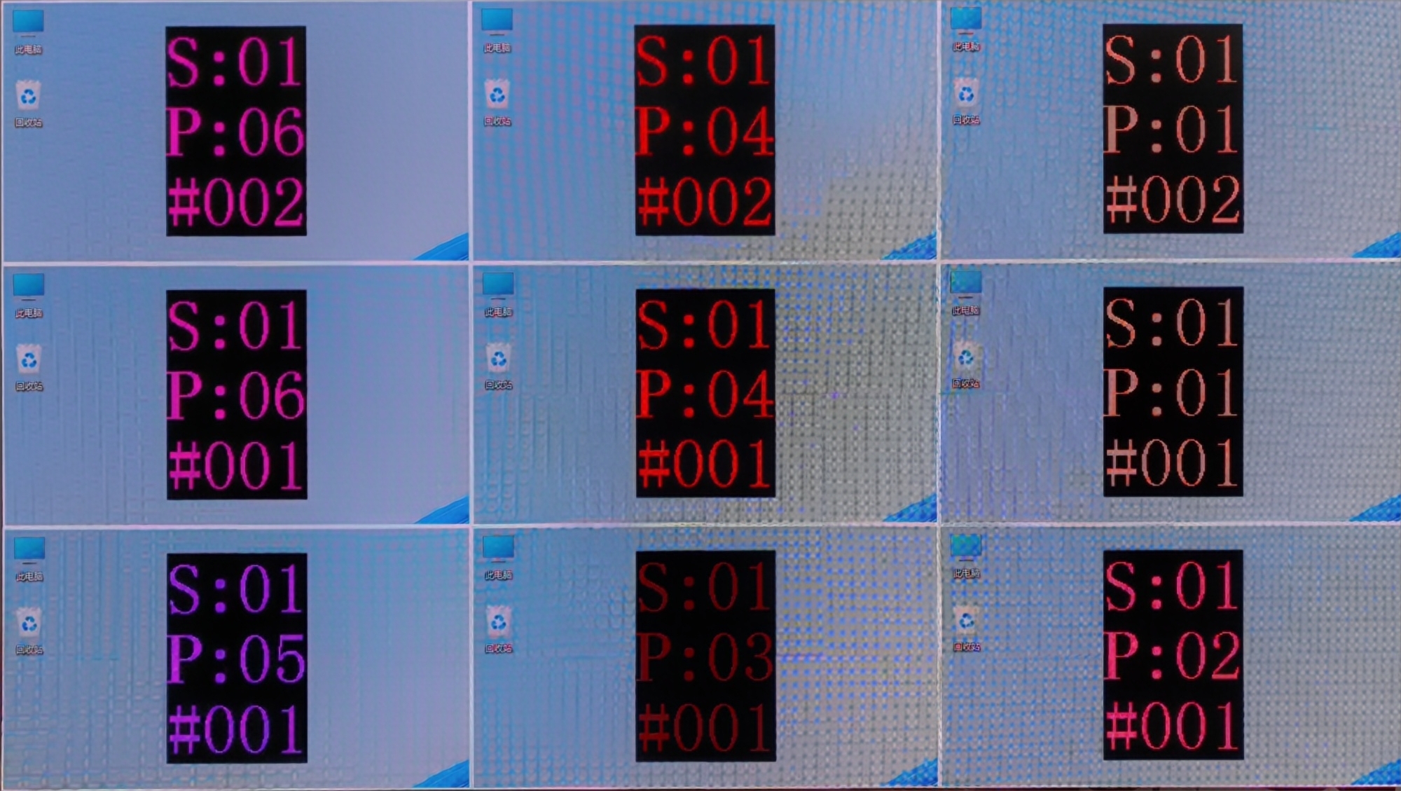
- Enable Mapping to view the physical arrangement of the cabinet.9(
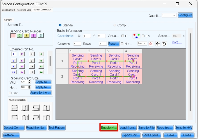
- Here, S represents the sending card number, P indicates the network port number on that sending card, and # denotes the cabinet number under that port. For example, S:01 P:04 #002 means the second cabinet connected to network port 4 of the first sending card.
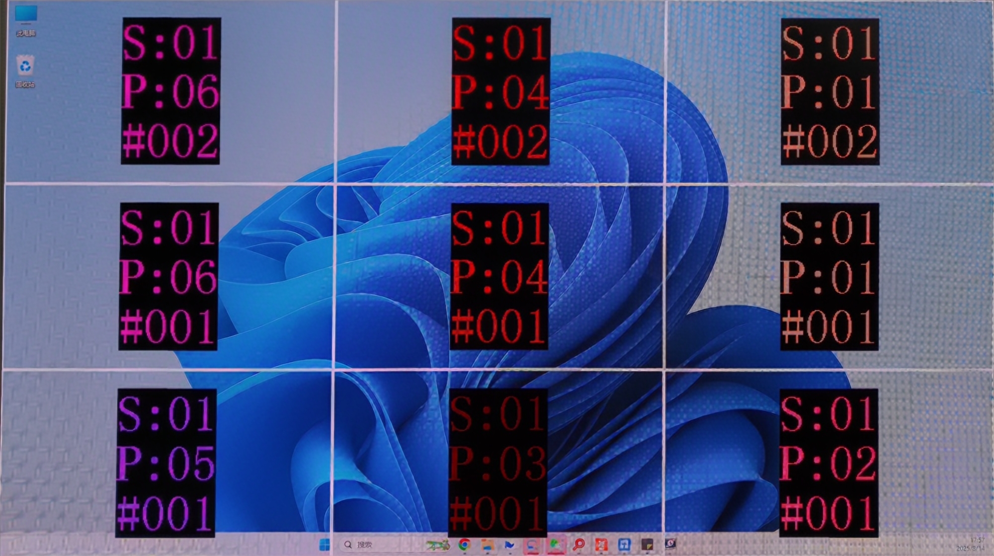
- Complete the cabinet connection according to the front view.
- After sending and saving, the screen will display as a completed image.Then disable Mapping.
Complex Screen Connection
Here is a example for complex screen connection
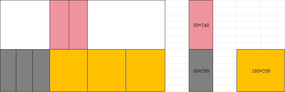
In complex screen mode, screen connection requires coordinate settings.
Complex Screen Connection is only for devices like the MCTRL series and TB series. If your project is important and large-scale, we recommend choosing the VX PRO series and COEX series.
In the screen connection interface, select the complex screen.
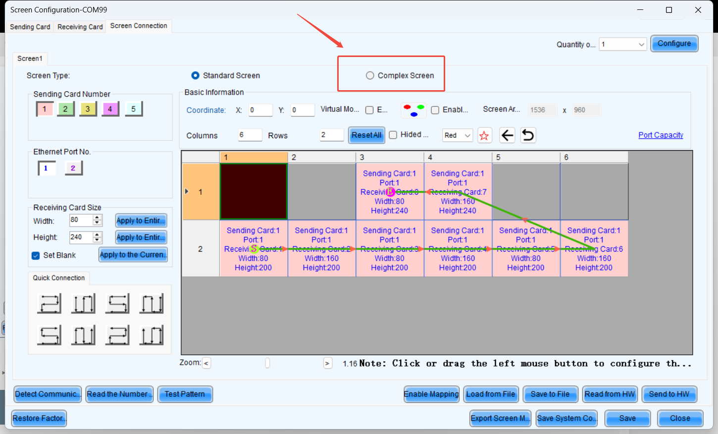
Since the height of the upper half is 240 pixels, the coordinates of receiving card 1 are (0, 240).
Similarly, the coordinates for receiving card 2 should increase by the width of receiving card 1 (80 pixels) along the X-axis.
Therefore, the coordinates for receiving card 2 are (80, 240).
The coordinate calculation logic for the remaining receiver cards remains the same as that of 1 and 2.
NOTE: Complex Screen Connection still has a rectangular load limit.
You also can move blocks with your mouse to align them.
Troubleshooting
3.1 The second output card of the H series displayed a black screen, but the screen control was functioning normally.
- Ensure that when does H-series screen connection, each output card corresponds to one screen. For example, if we use an H2 to drive a 7680x2160 screen, with each output card handling 3840x2160, the screen connection setup would look like below, ensure that the coordinates of all output cards start from (0, 0).
- The reason is that if multiple cards are configured within a single screen, all output cards except the first one on the left will experience coordinate offset. Additionally, Hweb will perform a splicing operation, causing a secondary coordinate shift and resulting in black screen issues.
3. Additional features
3.1. Multiviewer Setting
[Content to be added.]
3.2. 3D Setting
Software Configuration and Operation Guide
This section covers 3D settings on the software.
Enable 3D in NovaLCT
Run NovaLCT, select Screen Configuration > Sending Card, check Enable 3D, and click Set 3D Parameters to open the 3D parameter setting page.
Screen Configuration:
3.3. HDR
[Content to be added.]
3.4. Preset & Preset Playlist
Save Preset
After completing the layer settings, you can save the edited content as a "preset," allowing multiple presets to cover different usage scenarios.
- Step 1: On the Programming page, click Save Preset below the layer editing area to open the preset saving window.
Save Preset
- Fill in the scene name according to actual needs.
- Click "Save" to complete the scene saving.
- Click "Preset" on the left to open the scene list and manually switch between different scenes.
Preset switching
- The preset playback function allows you to play the presets automatically based on the set playback sequence and single preset playback duration. After the settings, the system will play the presets automatically with no manual operations required. On the Programming page, click Preset Playlist on the left to enter the preset playlistsettings page.
Set Preset Playlists
3.5. H Audio Setting
Set Output Audio
When H series device is installed with H_2xAudio input+2xAudio output card, the audio output is supported. When the audio adapter wiring is required, please refer to A Audio Adapter Wiring complete the audio connector connection.
- Step 1: Click Programming to enter the programming page.
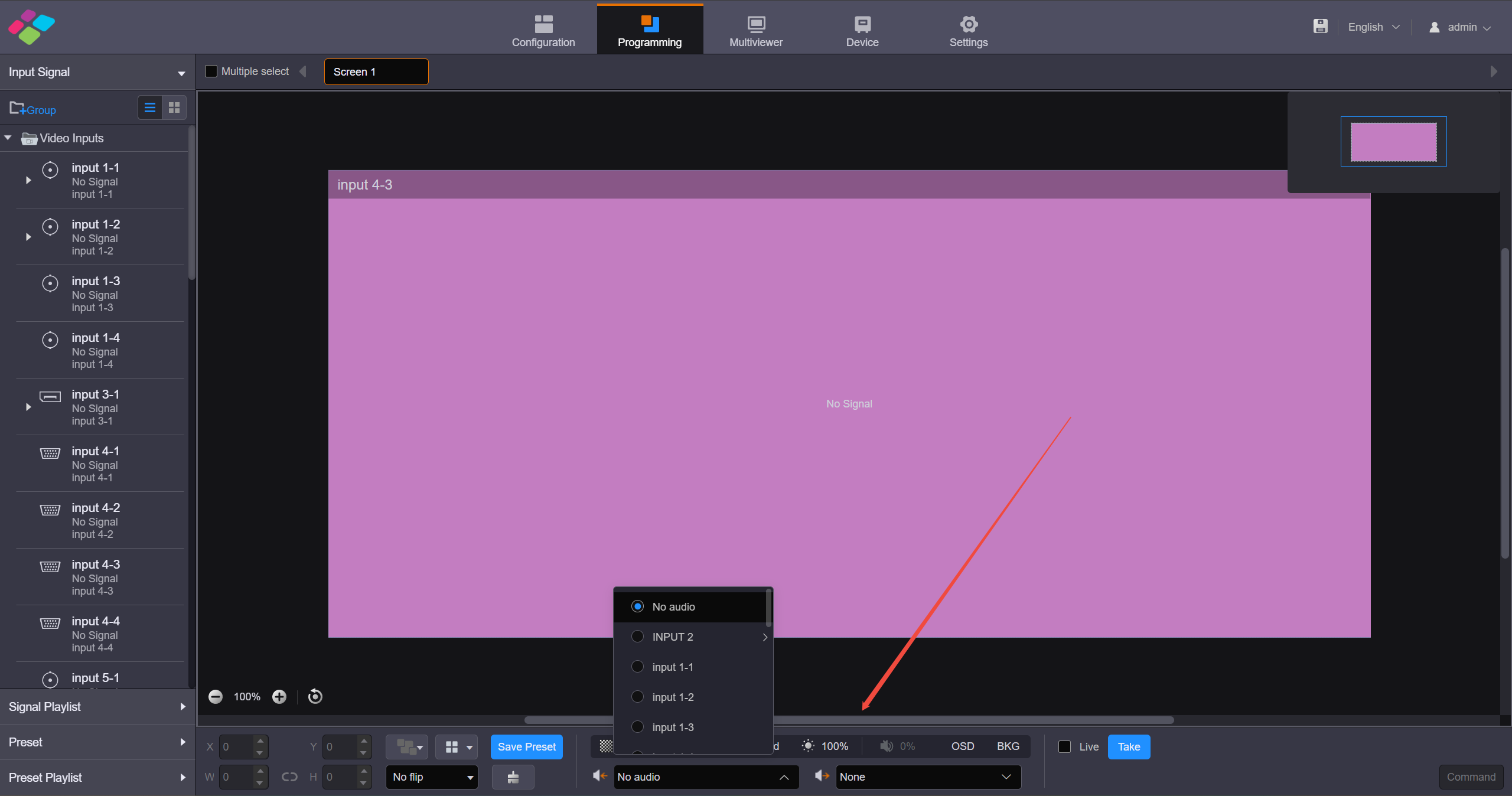
Set input and output audio
- Step 2: Set the input audio.
Click the dropdown box to the right of the audio input icon in the lower right corner and select the audio input source. Supported options include audio from the sound card input interface or accompanying audio from the HDMI input interface.
- Step 3: Set the output audio.
Click the dropdown box to the right of the audio output icon in the lower right corner and select the audio output interface. The sound card output interface is supported for audio output.
3.6. Backup Setting
H Series Device Backup Solutions
Output Card backup
Set the primary and backup for each output card separately.
On the WebUI, configure screens for both master card and backup card, placing the same layer.
*After the backup settings are completed, the backup ports will display a corner mark, which flash when the backup is in effect.
Device backup
Same as 3.2. Setup Steps
Precautions:
- The hardware configurations of the primary and backup devices are identical, with corresponding network ports;
- The same screen connection file is deployed, and the LCT sets the primary-backup relationship;
- The web configurations are exactly the same (the primary device configuration can be exported and loaded onto the backup device);
- Check the device backup option on the web interface for both primary and backup devices.
- Enable device backup in Settings to turn off the output when the input source is lost, otherwise, the primary/backup switch may have issues.
Backup Management
Click Backup Management on the left to enter the backup management page. You can save and export the configured device parameters as a configuration file for future use.
Import/Export Configuration Files
- Import Configuration File: Import the saved configuration file for quick screen configuration, color, EDID, layer, BKG, OSD, preset and preset playback settings.
- Export Configuration File: Click Export to export the device configuration parameters for future use.
Device Backup
When both the primary and backup sources fail, the device backup will take effect.
- The H series devices support both the backup between the devices and the backup between the sending cards on the same device. You must set the backup in NovaLCT by referring NovaLCT User Manual.
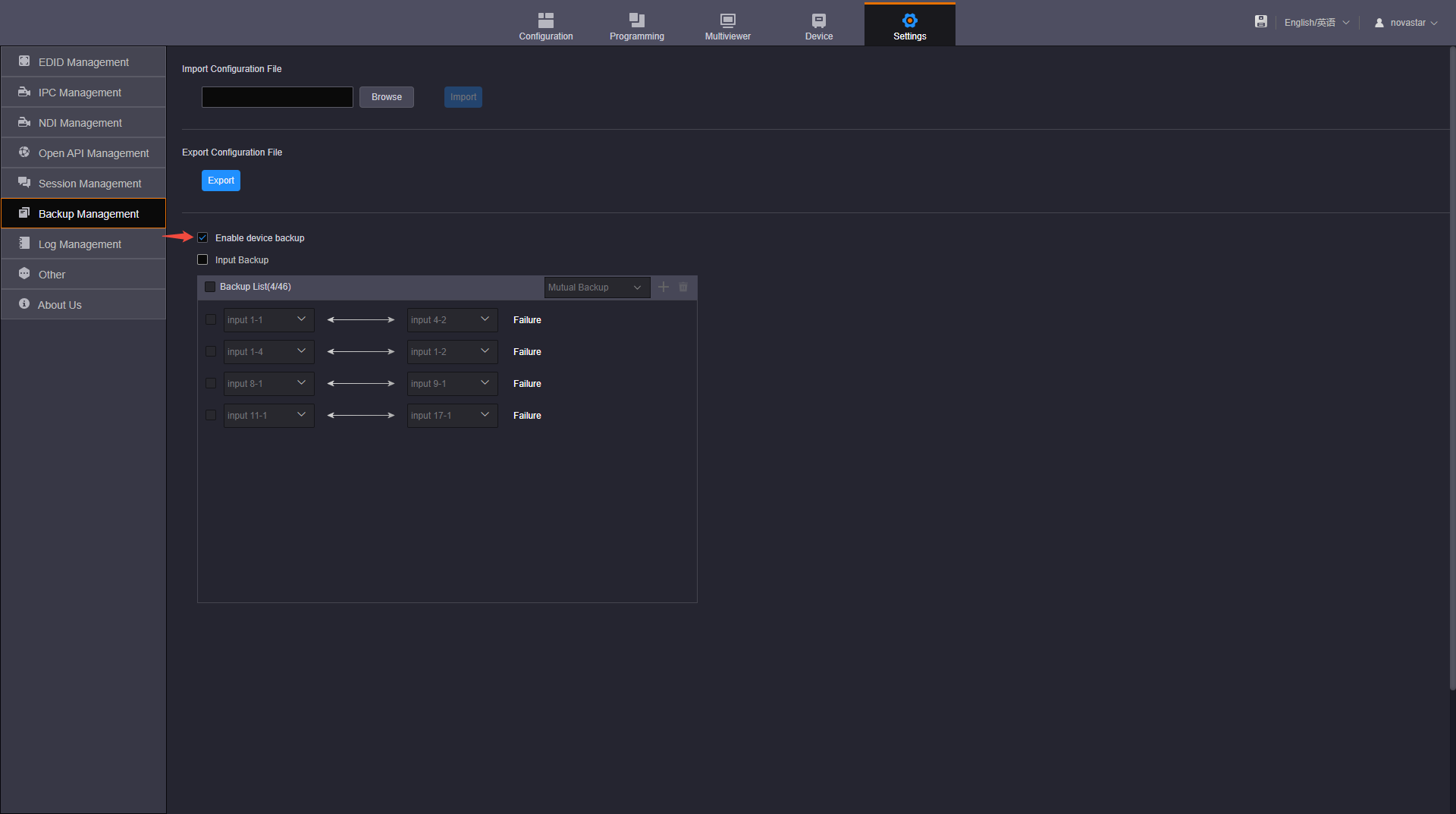
- After configuring the backup in NovaLCT, on the Backup Management page of each device, check the box in front of Enable device backup to turn on the backup function.
Input Backup
The H series devices support the input source backup function. If the input signal in use is abnormal or lost, the backup one will take over the job seamlessly to ensure the display not go black. The backup relationship cannot be set for NDI or IPC sources.
- Step 1: Click Backup Management on the left to enter the backup management page.
- Step 2: Check the box next to Input Backup to enable the input source backup function.
- Step 3: Select the desired backup relation. The options include Mutual Backup and Primary and Backup. Mutual Backup: When one input source fails, the other one takes the job seamlessly; when the failed one resumes, it continues to work normally and the other does not work. Primary and Backup: When the primary input source fails, the backup one takes the job seamlessly; when the primary one resumes, it continues to work normally and the backup one does not work.
- Step 4: Click Add at the top right of the input backup list to add a new backup pair.
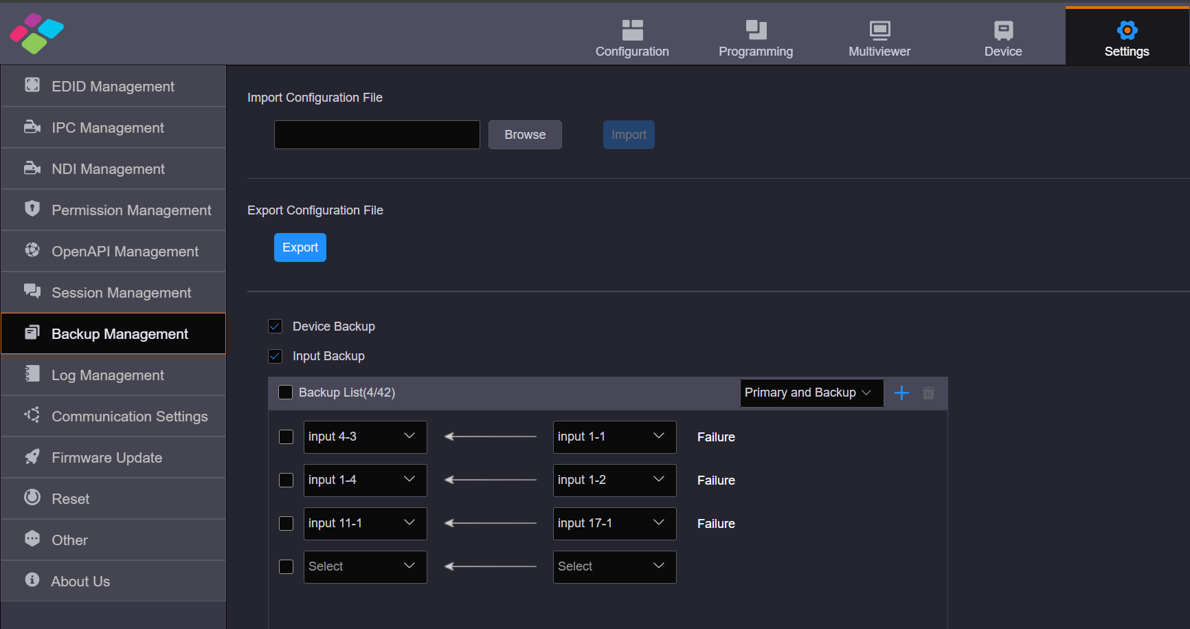
Add backup
- Step 5: Select two input sources respectively from the two drop-down lists to complete the adding of one backup pair.
- Step 6: Repeat Step 4 and Step 5 to add more backup pairs.
3.7. Brightness Setting
For NovaStar H Series Flagship Video Splicing Processor
- The H series mainline program (v1980 and above) supports hardware-scheduled brightness adjustment.
- When using the light sensor for brightness adjustment in the mainline version, it is necessary to keep the NOVA LCT software running continuously.
- If you need to adjust rhe brightness automatically only by light sensor, please contact Novastar engineer to get the custome firmware.
Hardware-scheduled brightness adjustment Usage Method:
Usage Notes:
-
When using this feature, please close the LCT software to avoid conflicts.
-
For chips such as ICN2053 and ICN2153, adjusting brightness actually modifies the gamma table. Please select the Special Adjustment Mode during configuration. For other standard chips, select Normal Mode.
-
When using hardware brightness adjustment, ensure that the hardware time is correct and synchronized with the actual time.
-
Brightness adjustment involves sending a brightness command once a scheduled time point is reached. To prevent issues—such as certain receiving cards not receiving the brightness command—you can configure multiple brightness adjustments within the same time period to ensure the screen adjusts to the correct brightness.
For example, if you need to set the brightness to 50% at 10:00, you can configure it as follows:
9:58 50%
9:59 50%
10:00 50%
10:01 50%
10:02 50%
3.8. Hweb Other Setting
IPC Management
When the user connects an IP input, IPC configuration is required for the input.
- Step 1: On the Settings page, click IPC Management on the left to enter the IPC management page.
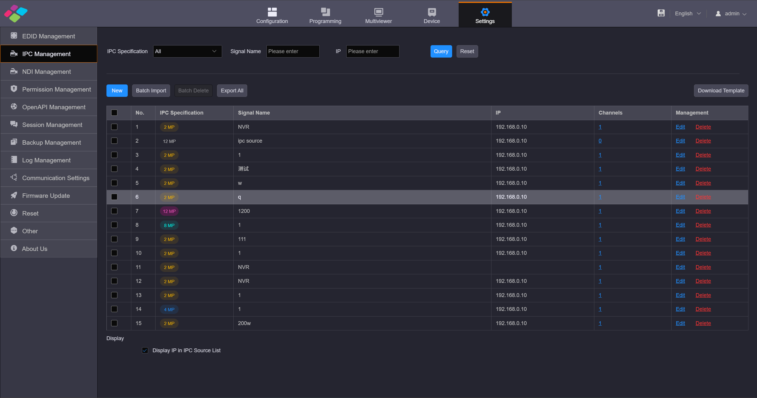
IPC management
- Step 2: Click New to open the Add Signal Source window.
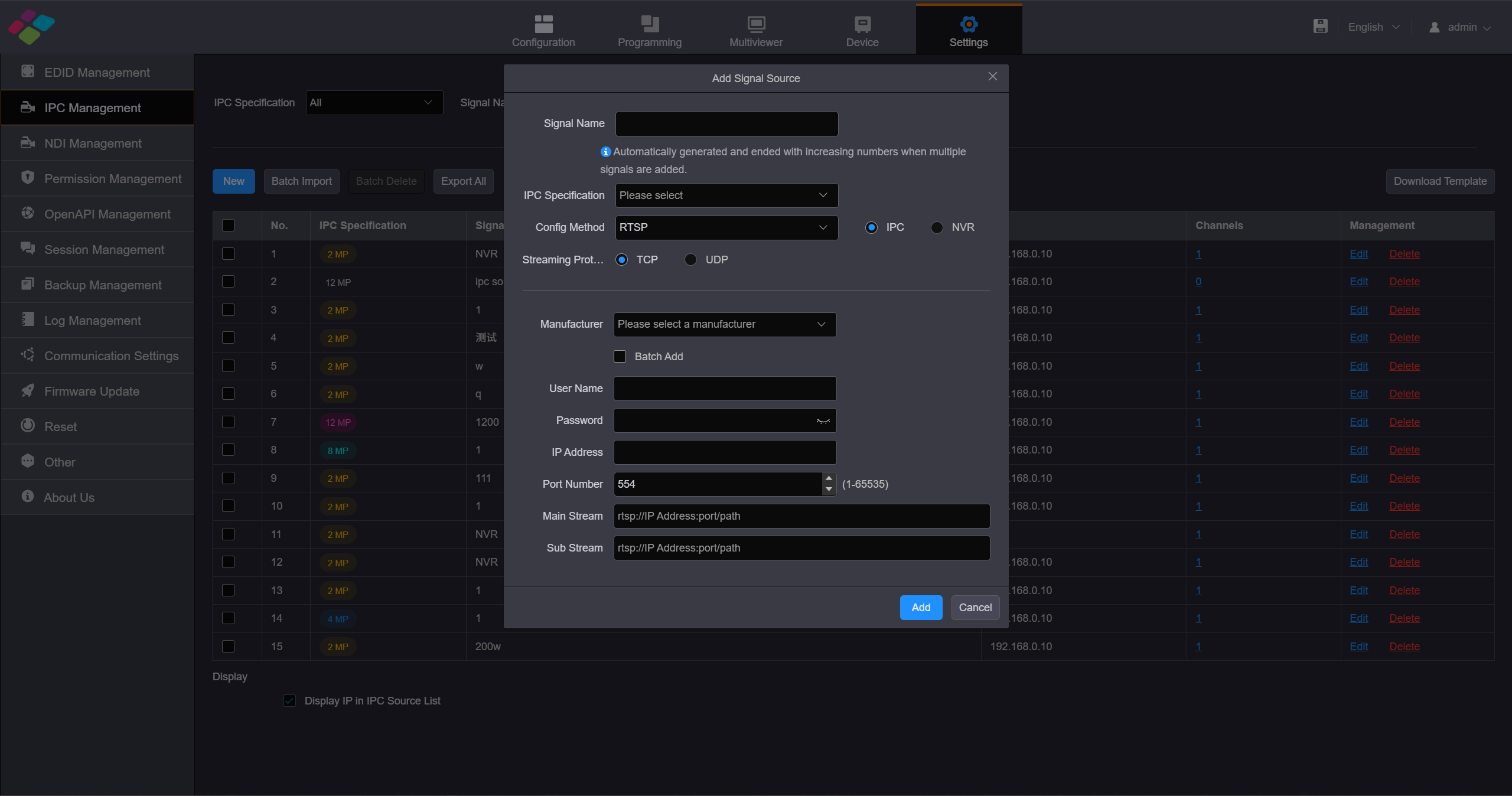
Add Signal Source
- Step 3: Enter a name for the added signal.
- Step 4: Click the drop-down list next to IPC Specificationto select the specification of the added signal. The supported options include 200W, 400Wand 800W. When you select the IPC specification,it must match the resolution of theIP camera. If the selected specification is lower than the resolution of the connected IP camera, the camera image cannot be decoded.
- Step 5: Click the drop-down list next to Config Method to select the input source protocol for the IPC card.GB28181, RTSP and ONVIF protocols are supported currently. When you select different protocols, you need to check the parameters of the added camera and then fill in the configuration parameters.
Config Method -RTSP
RTSP, which stands for Real Time Streaming Protocol, is used to transmit multimedia data over IP networks. When the " Configuration Method" is set to RTSP, it is necessary to obtain the camera's IP address, URL, username, and password in advance.
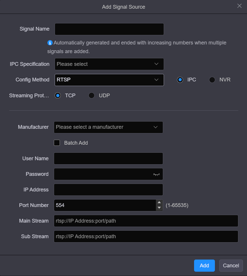
Method -RTSP
Config Method -ONVIF
ONVIF stands for Open Network Video Interface Forum.
Manual
- When you set the adding method to Manual, you must enter the camera IP address and the user name and password for logging in camera.
- When you check the box next to Add Multiple, you must enter the start and end IP addresses of the camera.
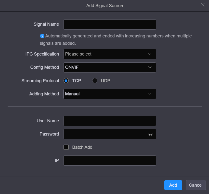
Method -ONVIF Manual
Auto scan
When you set the adding method to Auto scan, the system will scan and list all the cameras on the current network segment.
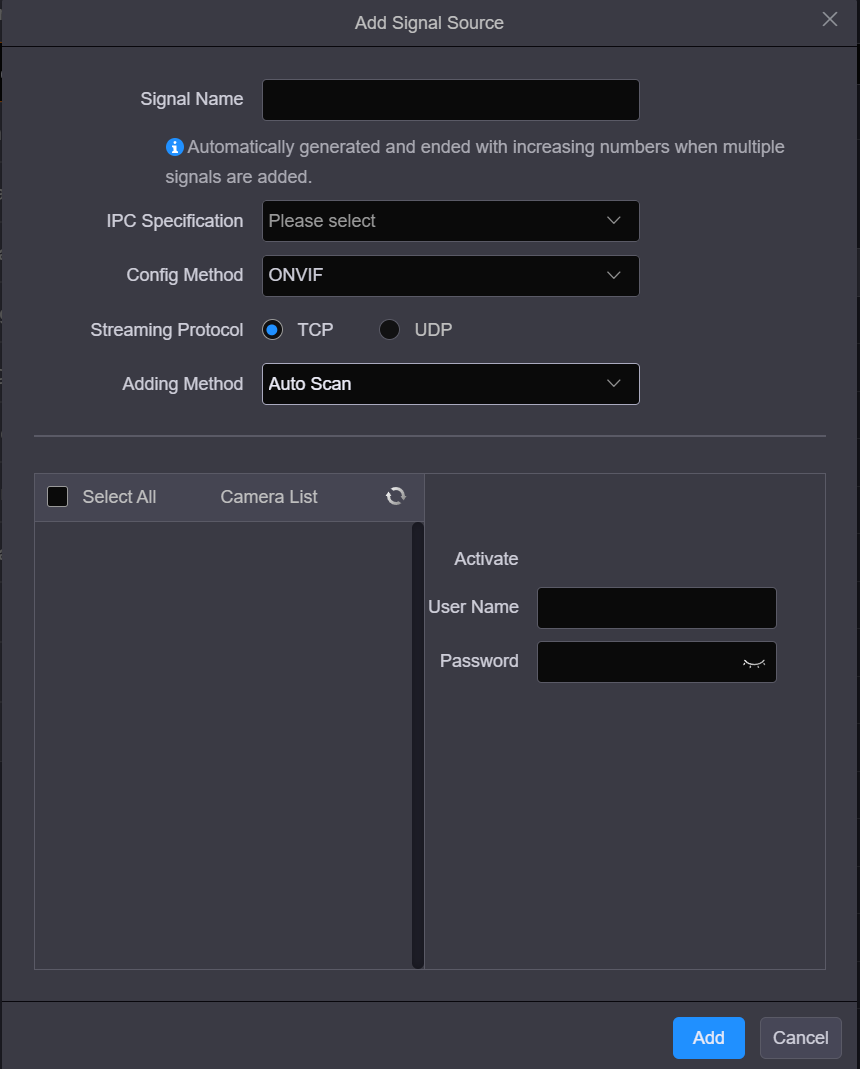
Method -ONVIF Auto scan
- Check the box in front of the desired camera, and enter the user name and password for logging in camera.
- When adding multiple cameras,you must set the same user name and password for the selected cameras in advance.
Config Method -GB28181
When you set the config method to GB28181, you must obtain the related information of the accessed monitoring system and the IP settings of the device in advance, and then fill the related parameters accordingly on the Web page.
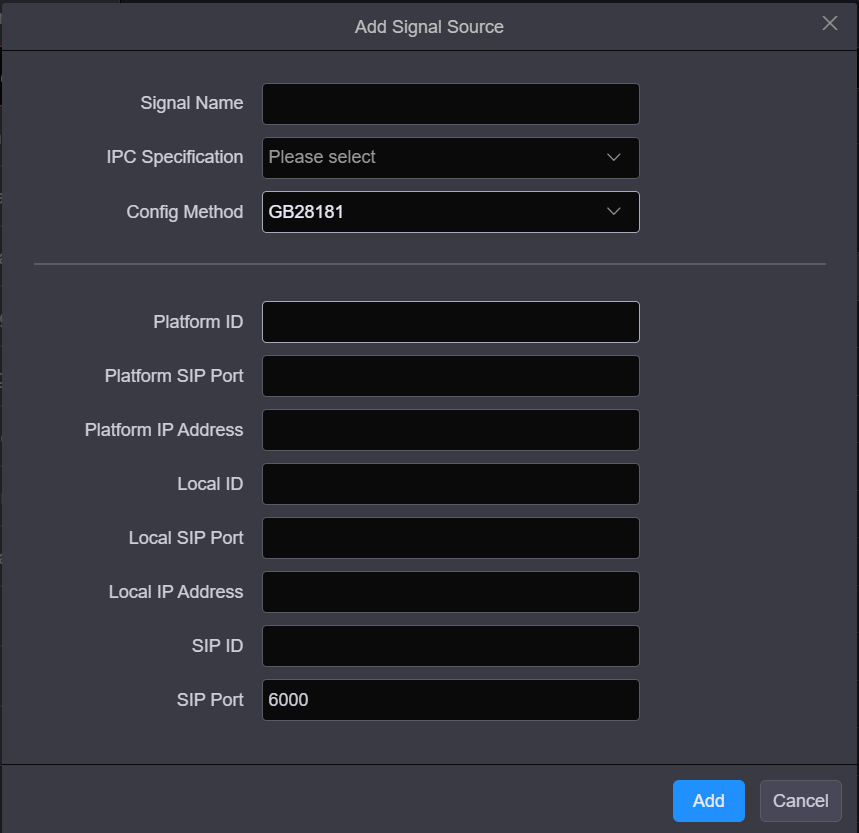
Config Method -GB28181
- Step 6: Click Add to complete adding the cameras.
After the video sources are added successfully, the cameras and their IP address will be listed.
- Step 7: Set whether to display the IP address in the IPC source list.
- Check the box next to Display IP in IPC Source List to display the IP addresses of the IPC sources.
- Uncheck the box next to Display IP in IPC Source List to hide the IP addresses of the IPC sources.
NDI Management
On the Settings page, click NDI Management to enter the corresponding page.
Add NDI source
Before adding NDI source, you need to connect the NDI connector to the local area network where the NDI source is located using an Ethernet cable, and set the decoding specification of the NDI card on the Device page.
Click New to open the NDI source adding window.
Add New NDI sources
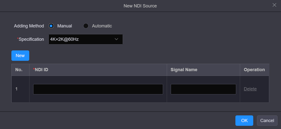
Add Manually
- Step 1: Select Manual next to Adding Method to open the corresponding window.
- Step 2:Select the decoding specification. The supported options include 4K×2K@60Hz, 4K×2K@30Hzand 2K×1K@60Hz.
- Step 3: Click Create to add a new NDI source.
- Step 4: Fill in the NDI source information. NDI ID: Enter the ID or IP address of the device providing the NDI source. Signal Name: Enter a name for the added NDI source.
- Step 5: Click Create to add more NDI sources and enter the source information.
- Step 6: Click OK to complete the adding.
Add Automatically
- Step 1: Select Automatic next to Adding Method to open the corresponding window.
- Step 2: Select the decoding specification and the system will automatically search for the NDI sources in the current environment.
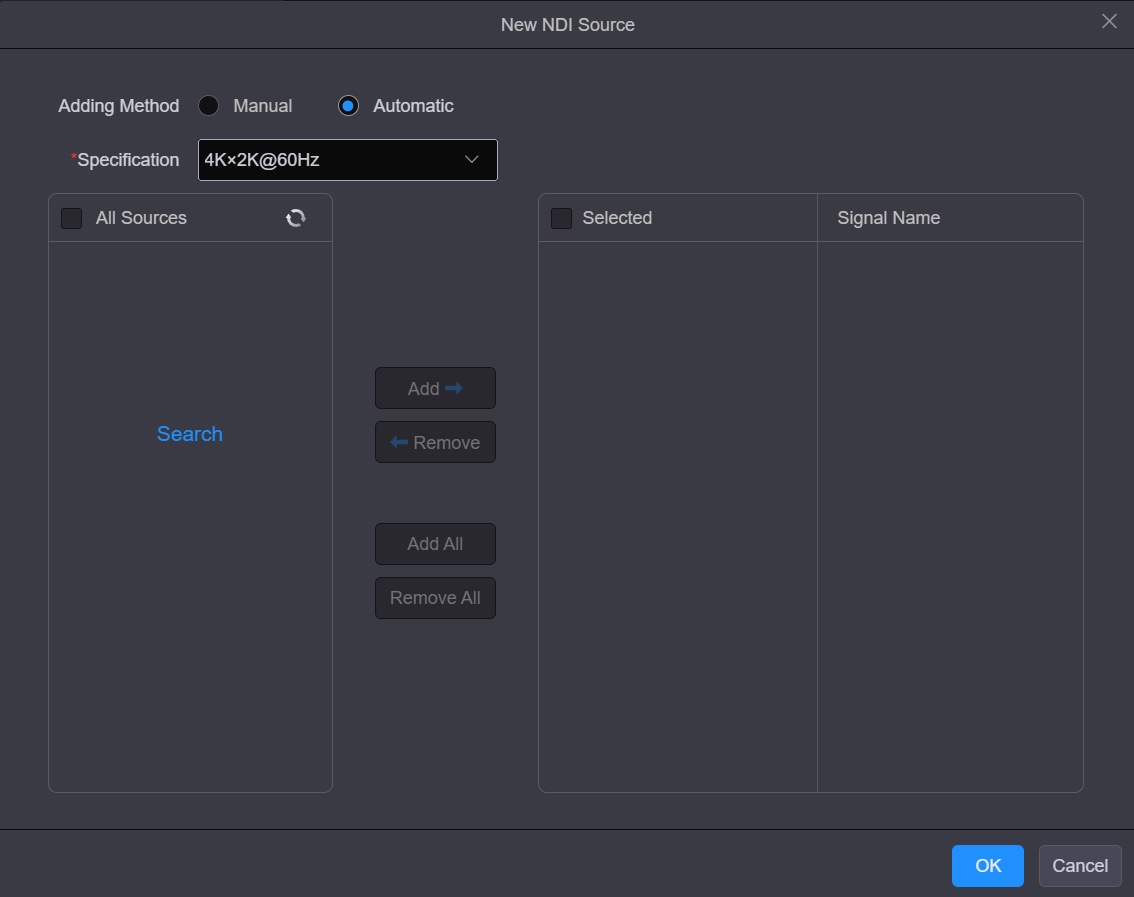
Automatically add NDI sources
- Step 3: In the All Sources area, check the box next to the desired NDI source.
- Step 4: Click Add to add the selected source to the Selected area.
- Step 5: In the Signal Name area, enter aname for the added NDI source.
- Step 6: Click OK to complete the adding.
Permission Management
Role Management
The administrator is able to create permission collections and grant permissions to each user in the system through the role management function. This function also facilities the fine control of user permissions.
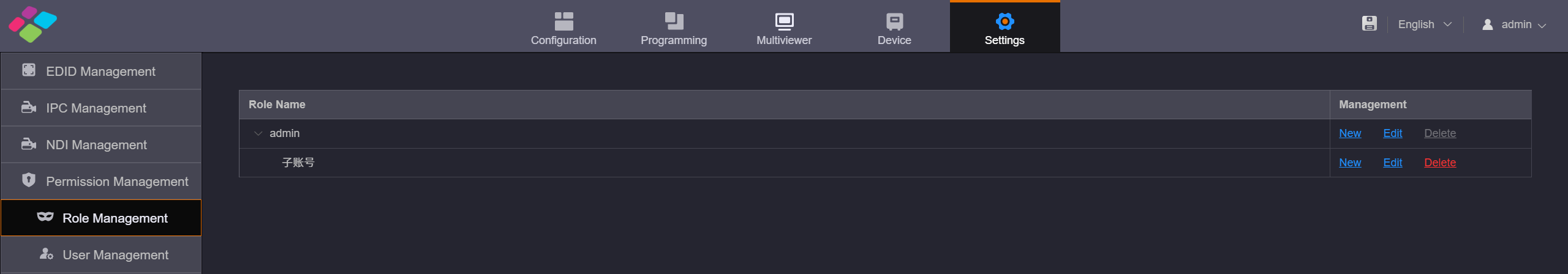
Role management
User Management
The H series supports multi-user collaboration at the same time. Only one user (admin) is created in the system by default.
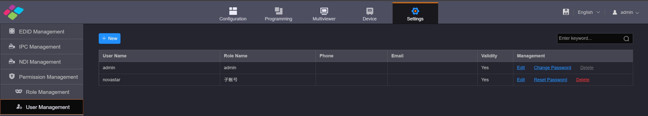
User Management
Session Management
Click Session Management on the left to enter the session management page. You can view the relevant informationof the current users in the system.
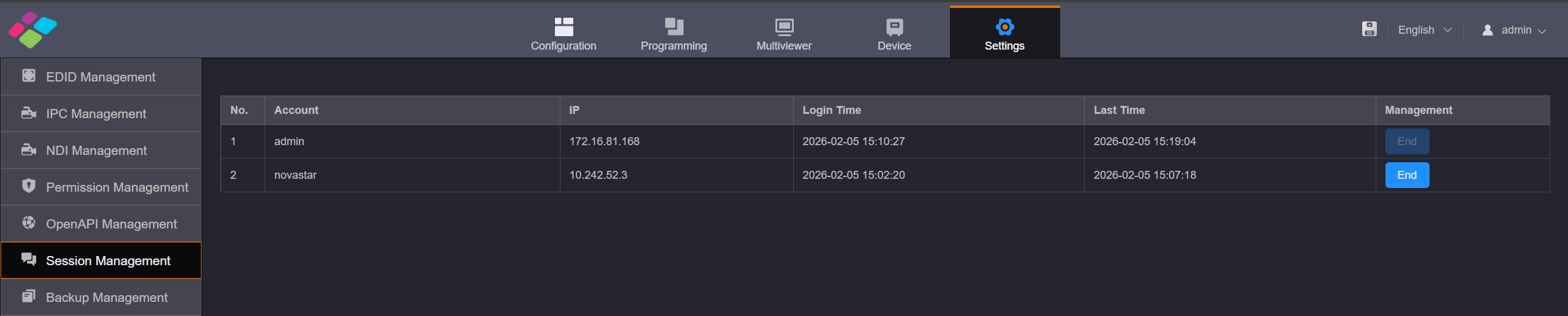
Session Management
If the user has the permission to end the session for other users, click End to force other users to log out.
Log Management
You can view the login logs and operation logs for analyzing problems.
Login Logs
Go to Log Management> Login Logs to enter the login log management page. You can view the IP address, login time and login status of each user.
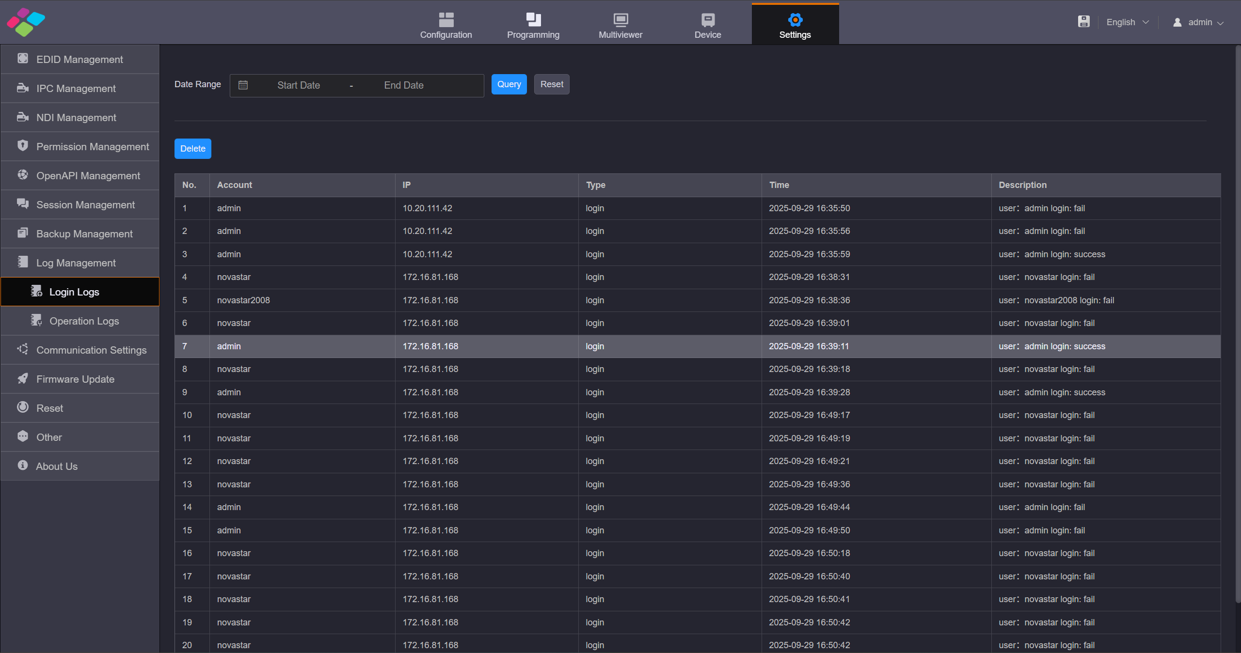
Login Logs
- Query Logs Select the start and end dates and click Query to query the login logs of the selected period.
- Delete Logs Click Deleteto delete all the login logs.
Operation Log
Go to Log Management> Operation Logs to enter the operation log management page.You can view the operation modules,operations, operation time and operation details of all the users.
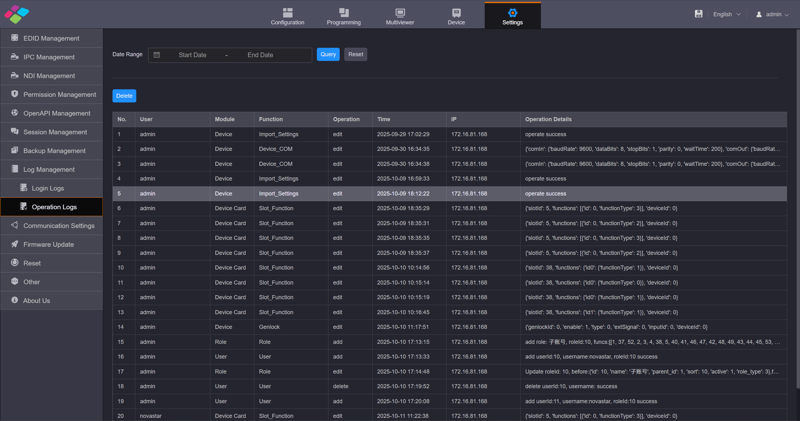
Operation Log
Communication Settings
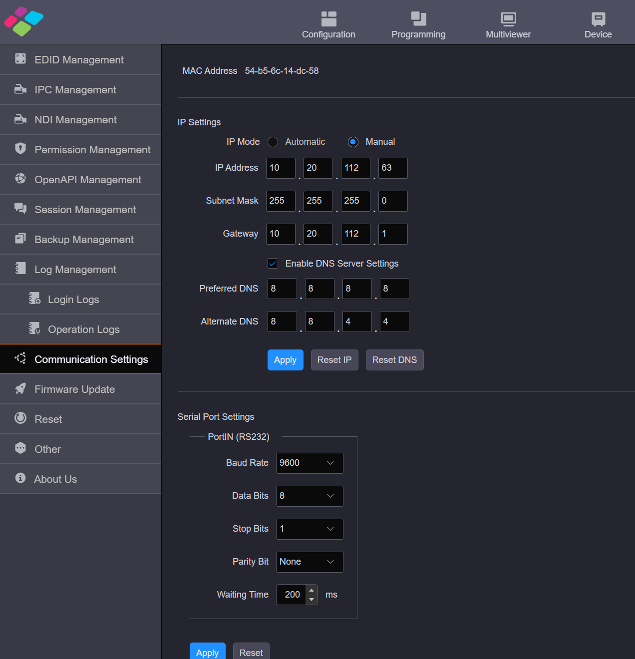
Click Communication Settings on the left to complete the IP address and serial port settings.
Communication Settings
IP Settings
- IP configuration supports both manual and automatic setup.
- When configuring the IP address, ensure that the device's IP address is set within the same subnet as the control computer's IP address but must not be identical to the control computer's IP address. For example, if the control computer's IP address is 192.168.0.100, the device's IP address should be configured as 192.168.0.X (where X cannot be 100).
- The subnet mask and gateway should match those of the control computer.
Set the DNS server
Set the DNS server for easyaccess to Internet resources.This helps to achieve the functions such as system time synchronization, OSD weather data retrieval, and time update in time OSD.
- Check the box next to Enable DNS Server Settings to enable the DNS service.
- Enter the IP addresses of the DNS servers next to Preferred DNS and Alternate DNS respectively.It is recommended to use a reliable public DNS server, such as Google 8.8.8.8 and 8.8.4.4.
- Click Apply to make the IP address and DNS server addresses take effect. Click Reset IP to reset the IP information, including the IP address, subnet mask and gateway. Click Reset DNS to reset the IP addresses of the preferred and alternate DNS servers.
Serial Port Setting
Set the serial port(COM IN)related parameters for a better connection with the central control device and device control through the central control device.
Set Serial Port Parameters
The H series devices support the control of other devices via the COM OUT port on the H_Control card. The serial port (COM OUT) is used to connect the controlled device. You need to obtain the serial port parameters of the controlled device before settings.
- Step 1: Click Communication Settings on the left to enter the communication settings page.
- Step 2In the Command Settings area, set the serial port parameters. Each serial port parameter must be the same as that of the controlled device.
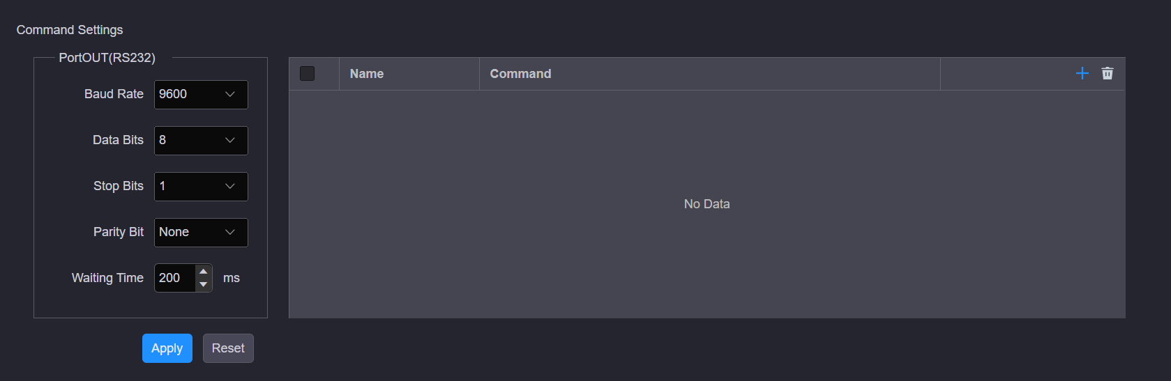
Serial port parameters
- Step 3: Click Apply to save and apply the settings.
Reset Settings
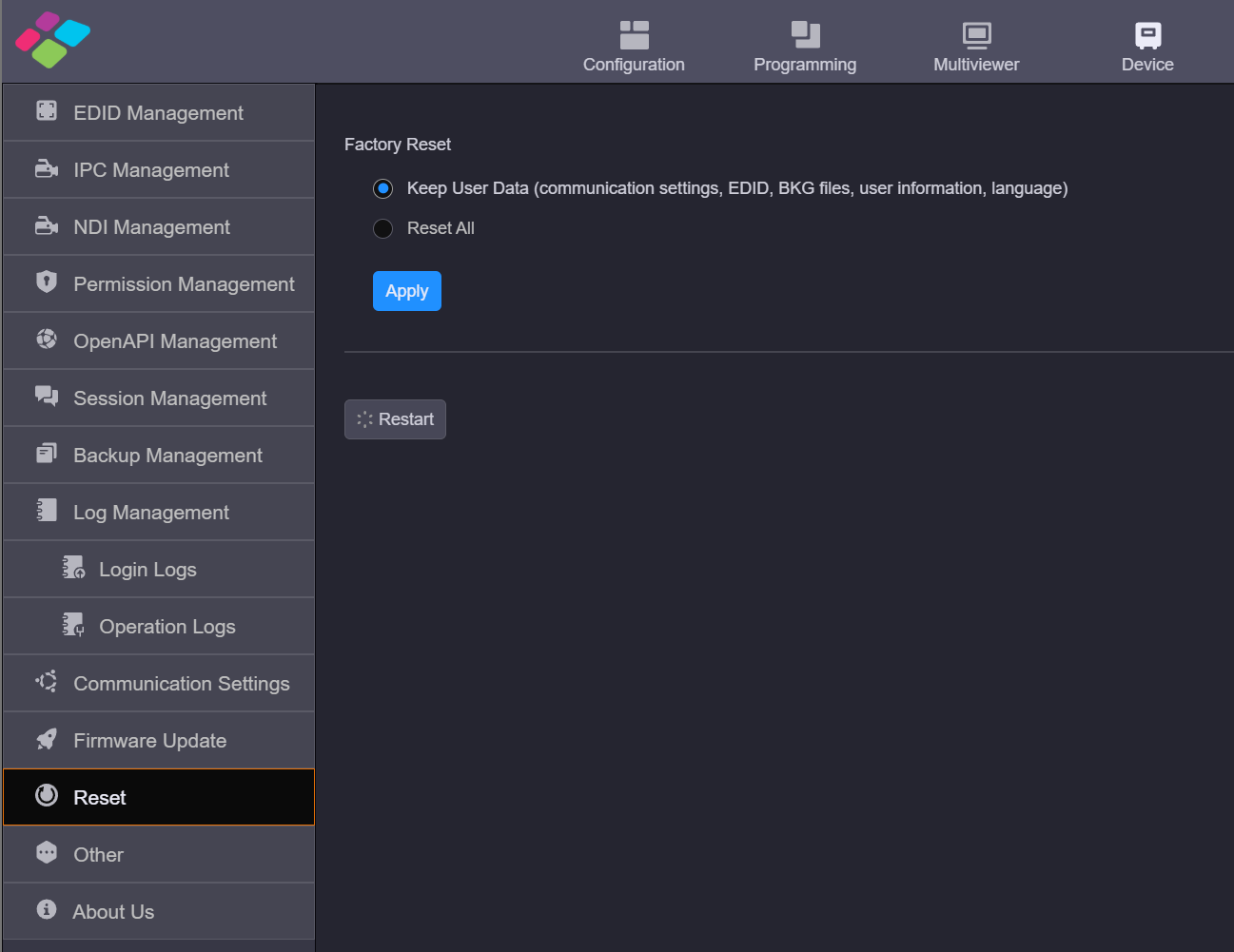
You can reset the device configuration data to factory defaults.
Reset
Factory Reset
Select the desired reset mode and click Apply.
- Keep User Data: When you reset the device, the following information will still be kept in the system, including the communication settings, EDID, BKG files, user information and language settings as well as other user data.
- Reset All: Reset all the parameters to factory defaults. When you select Reset All, the language settings screen will be displayed on the device LCD screen and Web page after the device is started. Select the desired language and click OK to complete the language settings.
Restart
Click Restart and the device will restart automatically.
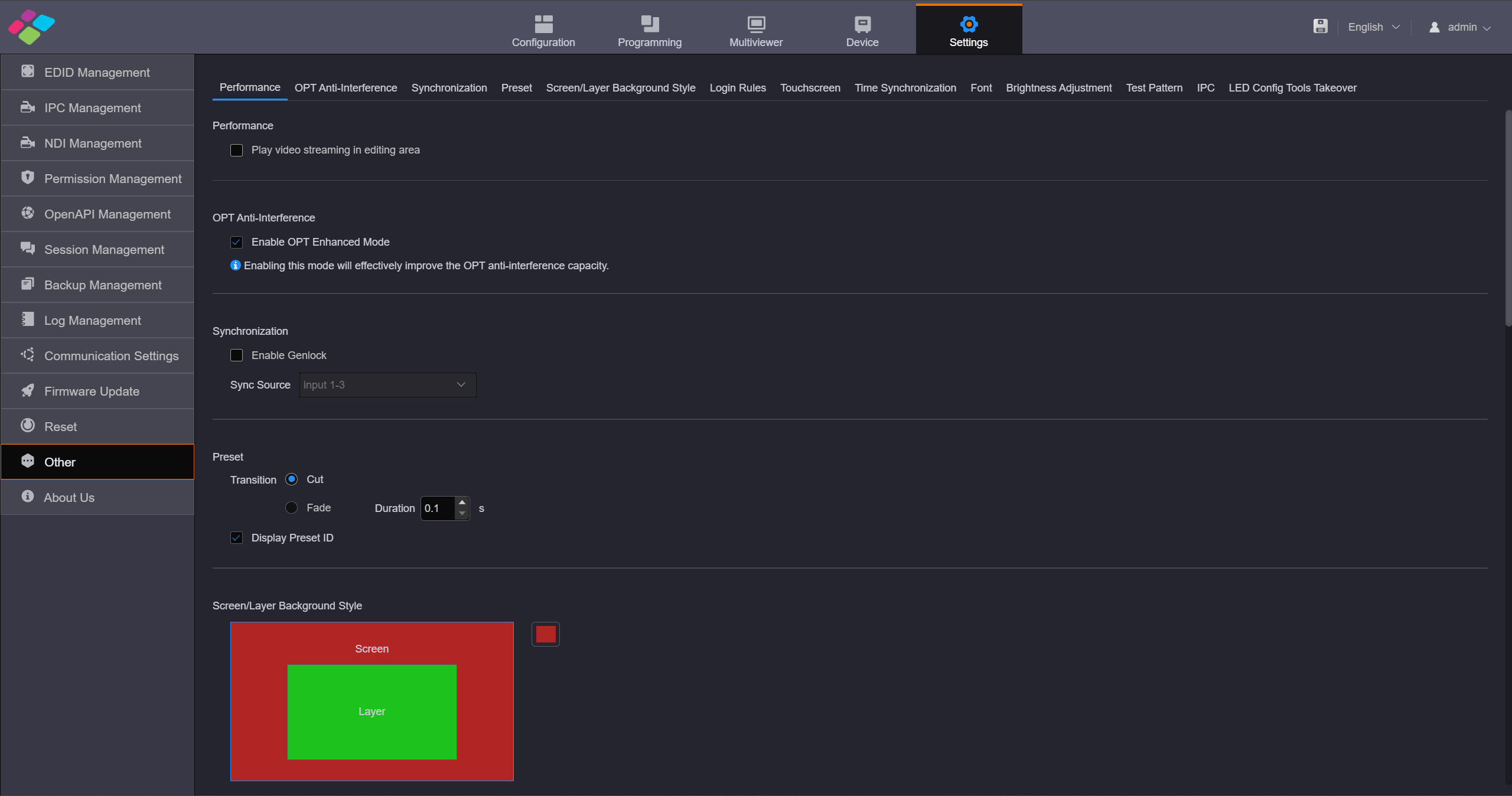
Other Settings
On this page, you can set the performance, Genlock and presettransition.
Other settings
Performance
Set whether to play the video streaming of the layer in the editing area. Turn off this function for quicker layer configuration.
OPT Anti-Interference
Enable or disable the OPT anti-interference function of the H_4xfiber sending card and H_16xRJ45+2xfiber sending card.
Synchronization
- Enable Genlock: Set whether to use the external Genlock sync source. Select Enable Genlock to turn on the Genlock function. Deselect Enable Genlock to turn off the Genlock function.
- Sync Source: Select the connected input source used as thesync source.
About Us
On this page, you can view the information such as the official website, email address and device version.Click Download Log to download the device operation log. When the device fails, you can download the log and send it to your device manufacturer for analyzing problems and offering suggestions to fix the problems The logs in this section are different from the previously mentioned login logs and operation logs; these are system runtime logs.
3.9. H API
Open API Management
The H series offers open API interfaces and supports third-party developers in obtaining authorization to control the H series video wall servers through these API.
- Step 1: Click Open API Management on the left to enter the open API management page.
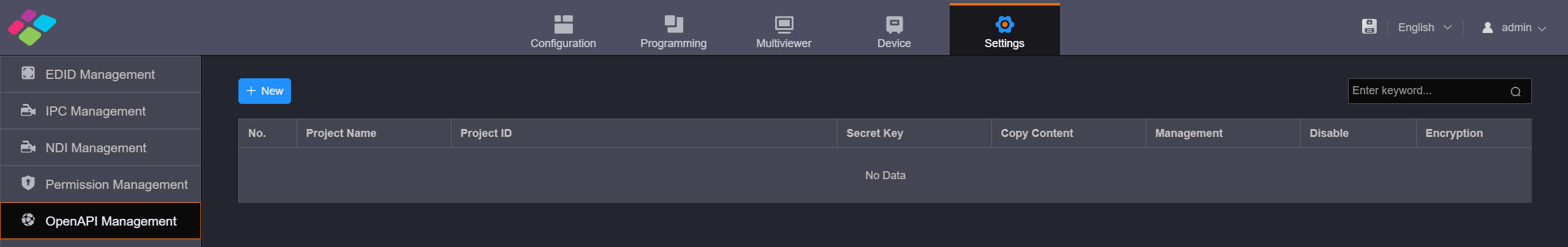
Open API management
- Step 2: Click New to add a new open API project.
- Step 3: Enter the name of the third-party control in the Project Name text box. The system automatically generates a secret key and display it in the Project Secret Key text box. Click Refresh to generate a new key.
- Step 4: Click OK to complete the adding. After the API is added, the system will automatically create a project ID, and the API is enabled by default. When encrypted transmission of control commands is required, click the toggle switch under "Enable Encryption" to turn on encrypted transmission. Click "Copy" in the project to copy the project name, project ID, and key information, making it easy to share with third-party developers. When the Open API is no longer needed and the created API project needs to be deleted, first set the "Enable" status of the project to disabled, then click "Delete" in the project to remove the API information.