MCTRL Series
Additional Features
1. MCTRL Configuration Preparations
This section details the physical connection process, including power, video inputs/outputs, and control interfaces.
1.1. Hardware Connection
- Power Connection: Connect the provided power cord to the device's power input and plug it into a power outlet.
- Video Input Connection:
- Connect the HDMI/DP/DVI output from your video source (e.g., a computer, media player) to the processor's input ports using the appropriate cables.
- ❗ Warning: Ensure the input signal resolution and refresh rate are within the device's supported range.
- Video Output Connection:
- Connect the processor's output ports (typically RJ45) to the cabinets.
- Control Connection:
- Use a network cable to connect the device's RJ45 control port or USB Type-B port to your computer's network port or USB port for software control.
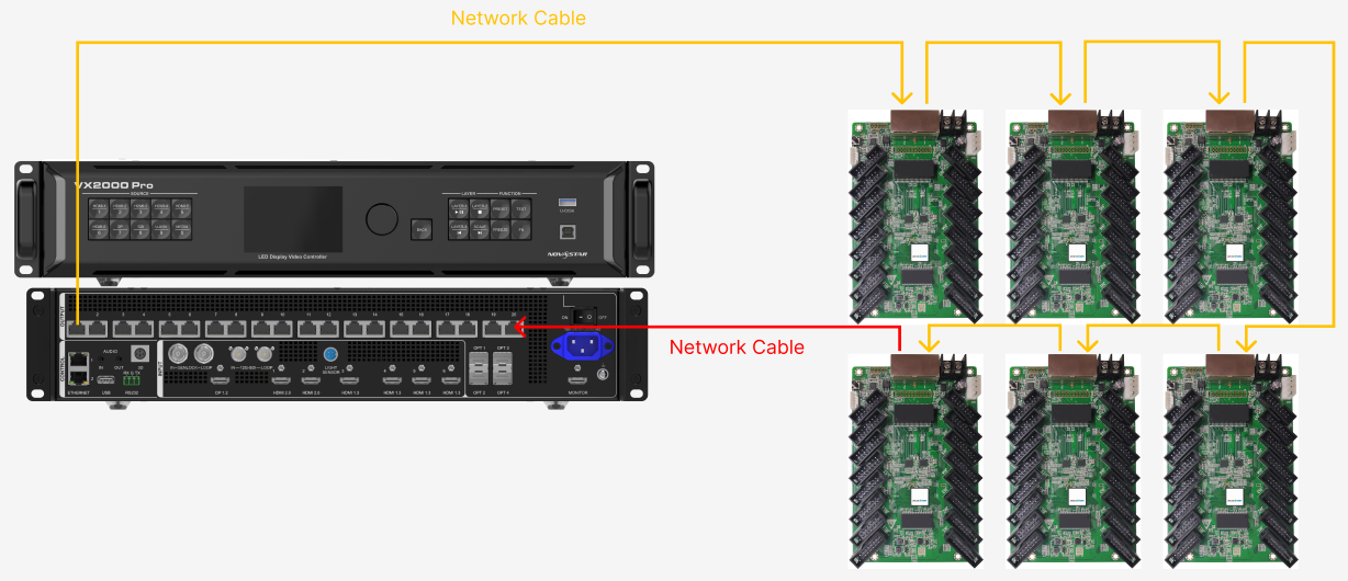
- System connection reference
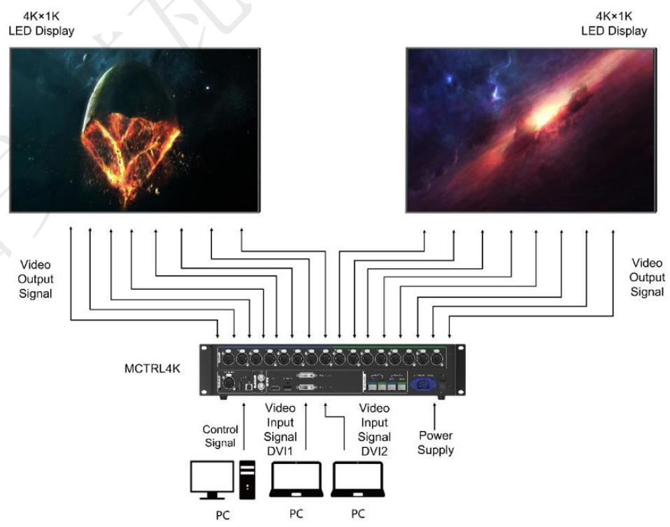
System connection reference
1.2. Device Communication Setting
This document introduces the communication settings before system configuration and lists some common issues along with their solutions.
1.2.1. Sending Card Communication Settings
- Topology of USB connection and cascading.
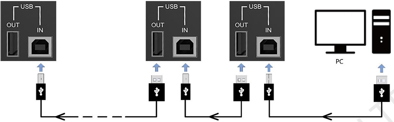
USB connection and cascading
The maximum cascading number of devices varies by model:
| Model | MCTRL 300/500/600/660/700 | MCTRL 660Pro | MCTRL R5 | MCTRL 4K |
|---|---|---|---|---|
| Maximum cascading number | 20 | 8 | 8 | 10 |
⚠️ Note: The use of RJ45 control and then USB cascading is not supported.
- On the device LCD panel, switch the device to USB preferred mode.
- MCTRL300/500/510/600/700 does not involve this step because it only has a USB control interface. Just use USB connection directly.
USB preferred mode
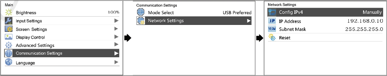
1.2.2. PC Network Settings
- Set a static IP in the computer's Network settings. For example, if the device is assigned 192.168.0.10, the computer can be set to 192.168.0.12 (which should be different from the device). Please note to identify which interface you're using; when multiple interfaces are in use simultaneously, you can confirm by plugging and unplugging them.
- For Windows PC.
Windows PC network settings
- For Mac.
Mac network settings
2. NovaLCT Config
2.1. Input Setting
- Before we operate the software, there are several graphics card settings we need to check.
First is to make sure the PC is working in Duplicate mode, since it will help us to identify the screen content while doing screen connection. The short cut button for Windows system is "Windows+P".
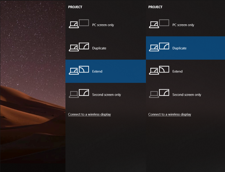
Duplicate mode
- Another thing is the scale and layout setting. To make sure the screen is displaying pixel by pixel, no scaling, no stretch. Right click the desktop and select the display setting, change the scale and layout to 100%.
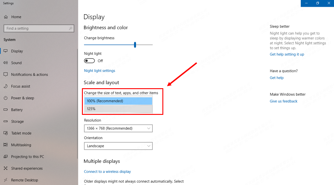
Scale and layout
- In the Sending card page:
- In order to set the screen display pixel by pixel, we should choose the correct video source, set the resolution same as the graphic card output resolution, and set Refresh Rate same as the input video source then click the Set button.
- The second step is to click Refresh to check whether the Sending card has been set successfully or not, you can see the information in the current display mode area.
- If everything is correct, click the Save button to save all to hardware.
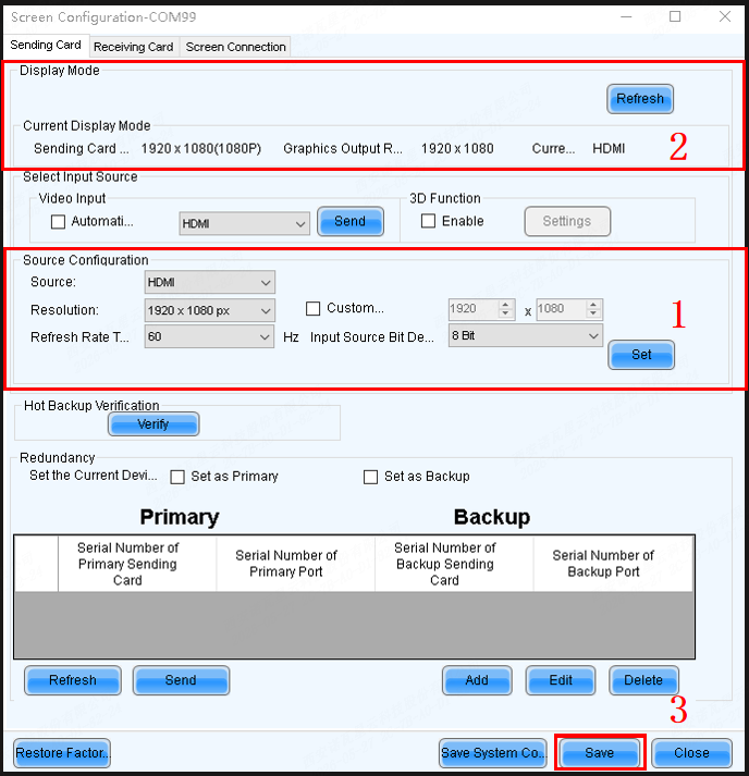
Sending card page
2.2. Cabinet Configuration
2.2.1. User Login
- When the device is from the MCTRL, VX, VX Pro, H, MEE, KT series, select Advanced Synchronous System User Login, with the default password set as admin.
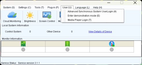
User login
2.2.2. RCFGX files
What is RCFGX file:
An .rcfgx file is a Receiving Card Configuration file used primarily by NovaStar LED display systems. It acts as a configuration profile, containing essential parameters like resolution, scan mode, pixel mapping, and refresh rate for LED panels.
Where can you get the file:
The RCFGX file is provided as a standard working file with the cabinet upon shipment. For additional files, you can contact the LED screen manufacturer's relevant staff to obtain them.
Load RCFGX file
- After that, you can import the exported RCFGX file into the new, unconfigured cabinet.
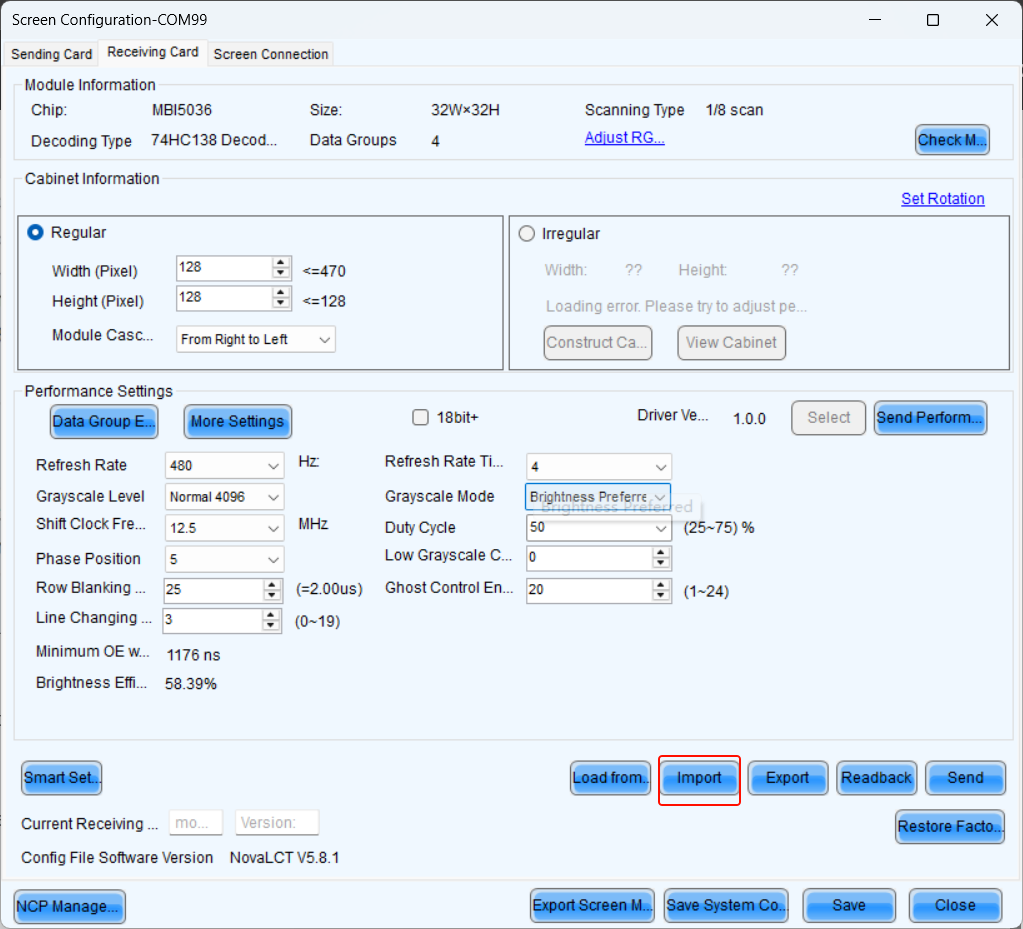
Click import
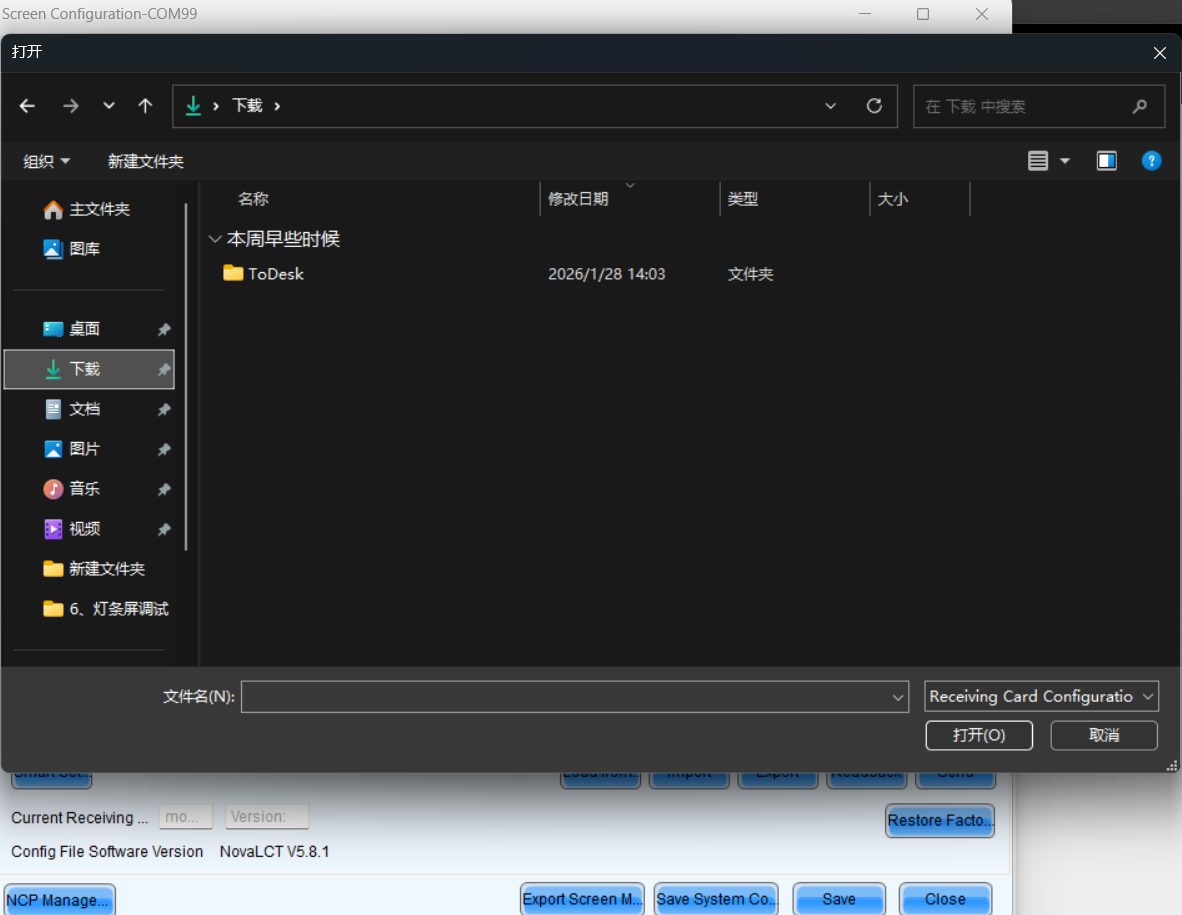
Choose the right file
Send RCFGX file
- After importing a new RCFGX file, the parameters will not be sent directly to the receiving card. You need to click the send button.
- Before saving to hardware, ensure the display is functioning perfectly.
- After successfully sending the parameters to the receiving card, click Save to store the parameters in the hardware, ensuring data remains intact after power cycling.
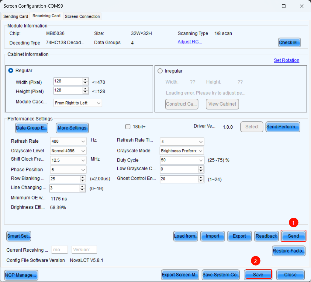
Send and save to HW
Save the RCFGX file to your local computer
- When you have a cabinet that is functioning properly, you can read back its parameters in LCT and save the RCFGX file to your local computer.
Save RCFGX locally
2.2.3. NCP files
1. What is NCP file:
You can click the link below to check the information about the NCP file.
2. How to send NCP file with NovaLCT:
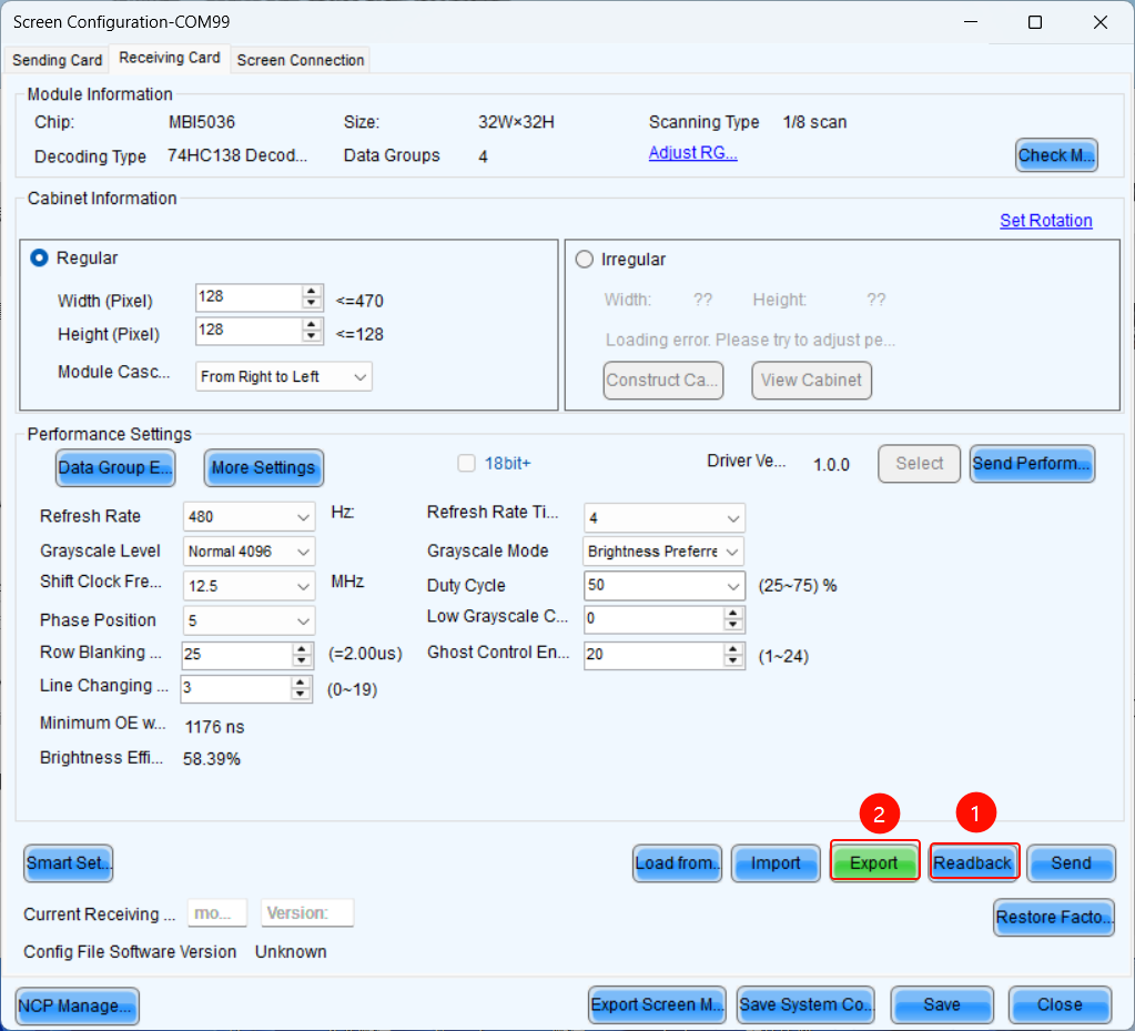
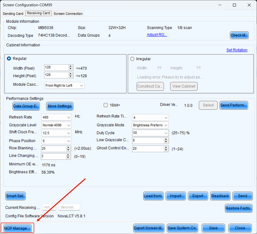
- Step 1: On the Screen Configuration page, click the Receiving Card tab for NCP Management.
If the Receiving Card tab defaults to the .rcfgx/.rcfg configuration interface, click NCP Management to enter the NCP management interface.
NCP Management
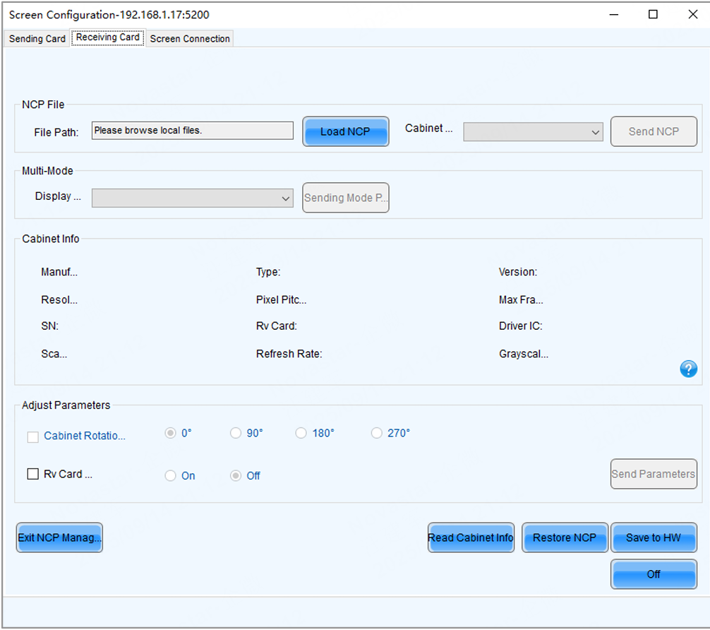
NCP Management interface
- Step 2: Click Load NCP.
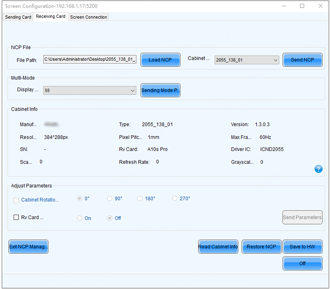
- Step 3: On the pop-up window, choose an .ncp file, and click Open.
- Step 4: Send the cabinet file and display mode parameters.
- Select a cabinet file from the drop-down list and then click Send NCP.
- Select a display mode from the drop-down list and then click Send Mode Parameters.
- Step 5: On the pop-up window, select the target receiving cards and click Send.
- All Receiving Card: Send the receiving card configuration information to all the receiving cards loaded by the current sending card. If you select Reset the Starting Coordinate of Receiving Card, the starting coordinates of all the receiving cards will be reset to (0, 0). As a result, all the receiving cards display the top-left image of the input source.
- Specified Receiving Card: Send the receiving card configuration information to the specified cards by sending card, by topology, or by physical address.
Send NCP
- Step 6: Click Save to HW.
- Step 7: Do the following as required.
Read cabinet information:
Click Read Cabinet Info, set the receiving card address on the pop-up window, and then click OK.
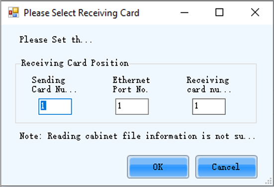
Read Cabinet Info
Restore NCP
a. Click Restore NCP. b. On the pop-up window, select the receiving cards you want to restore. c. On the Send by Topology tab, you can click Check Backup Files to check if there is a backup file in the receiving card factory area. d. Click Restore Specified Rv Cards to restore the backup file in the factory area to DDR. e. Click Save to All Rv Cards.
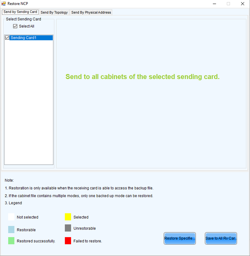
Restore NCP
Set cabinet rotation
Select Cabinet Rotation, set the rotation angle, and then click Send Parameters.
Set receiving card indicator
Select Rv Card Indicator, choose between Enable or Disable, and then click Send Parameters.
2.3. Screen Connection
Standard Screen Connection
- Click Screen configuration, then select the corresponding device IP or COM port, and click Next to enter the Screen Connection configuration interface.
Screen configuration
- Take a 3x3 LED screen as an example, the resolution of a single cabinet is 480x270px shown in the figure below.
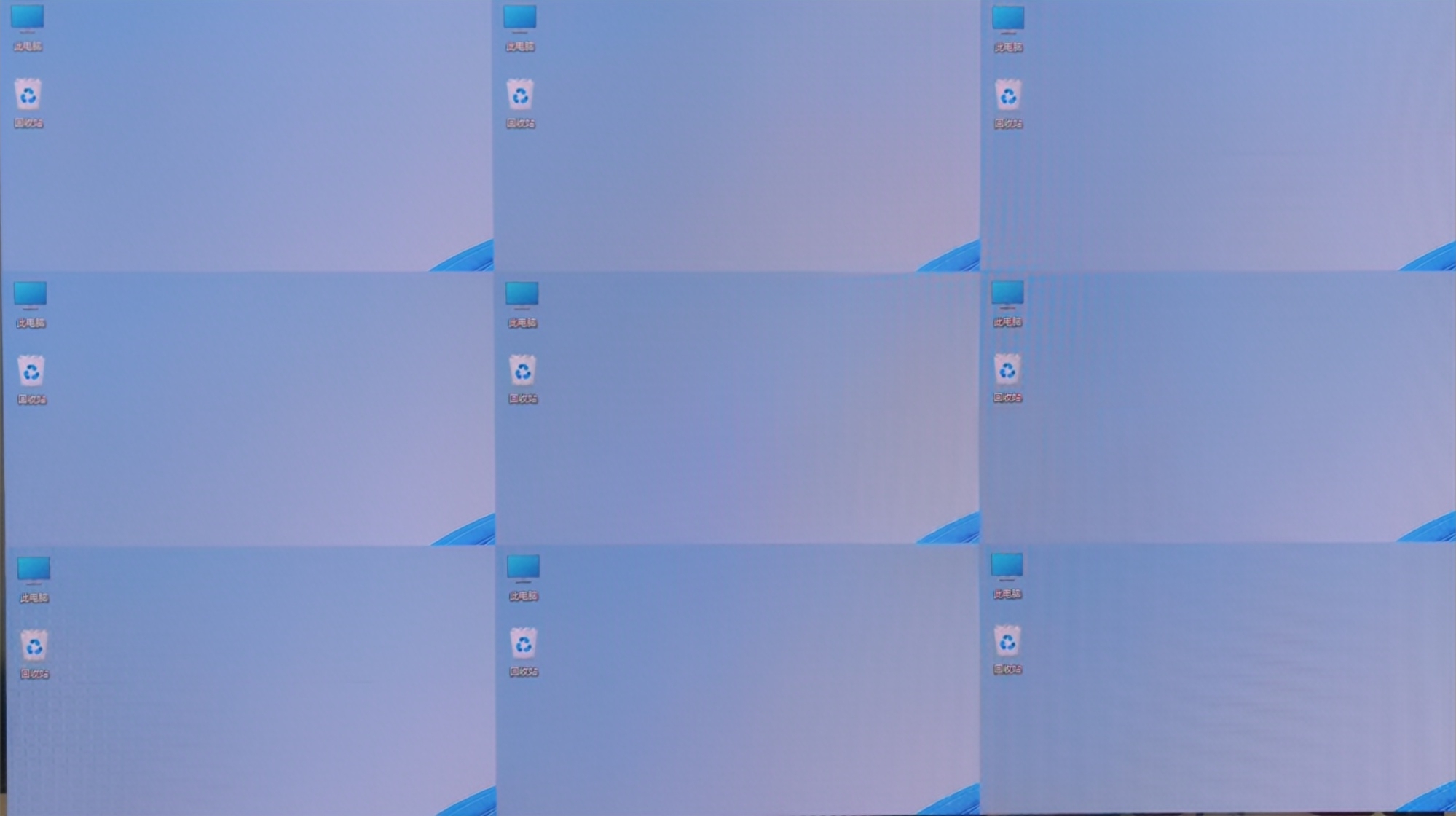
3x3 LED screen
- Enable Mapping to view the physical arrangement of the cabinet.
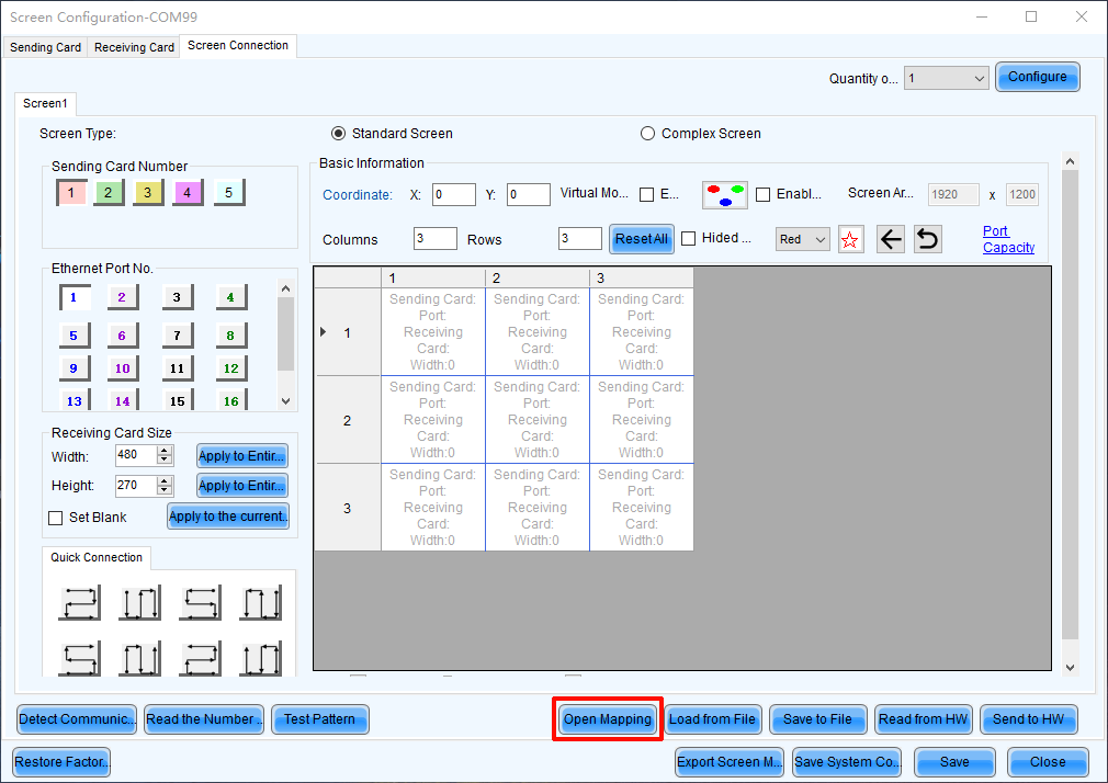
Mapping
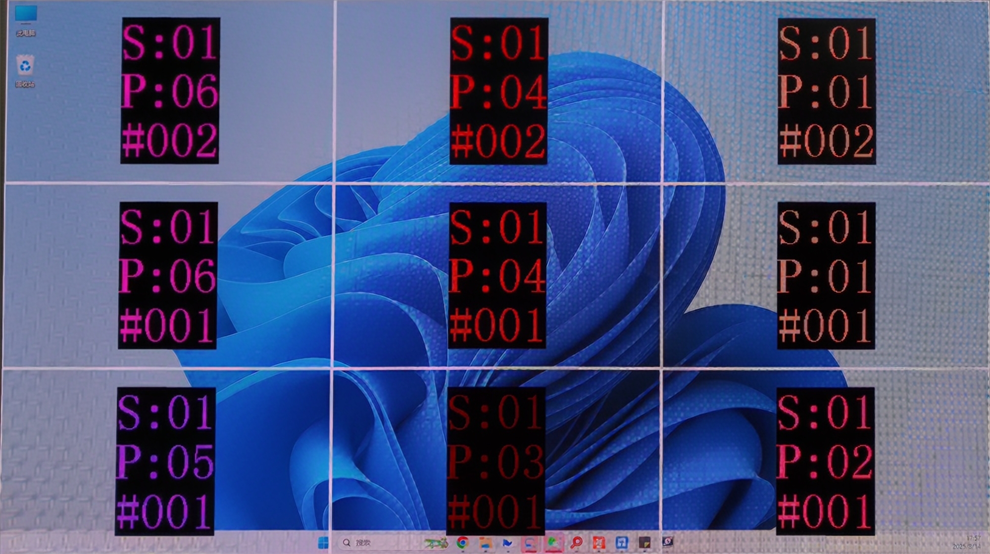
- Here, S represents the sending card number, P indicates the network port number on that sending card, and # denotes the cabinet number under that port. For example,
S:01 P:04 #002means the second cabinet connected to network port 4 of the first sending card.
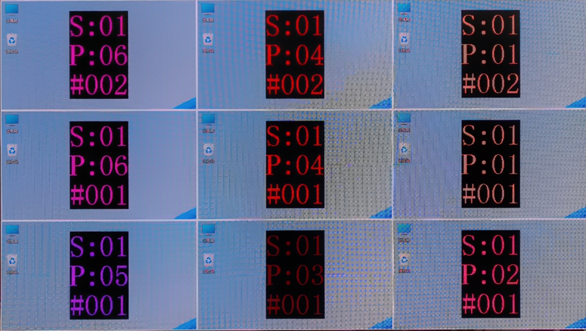
Cabinet mapping
- Complete the cabinet connection according to the front view.
Cabinet connection
- After sending and saving, the screen will display as a completed image. Then disable Mapping.
Completed screen
Complex Screen Connection
Here is an example for complex screen connection.
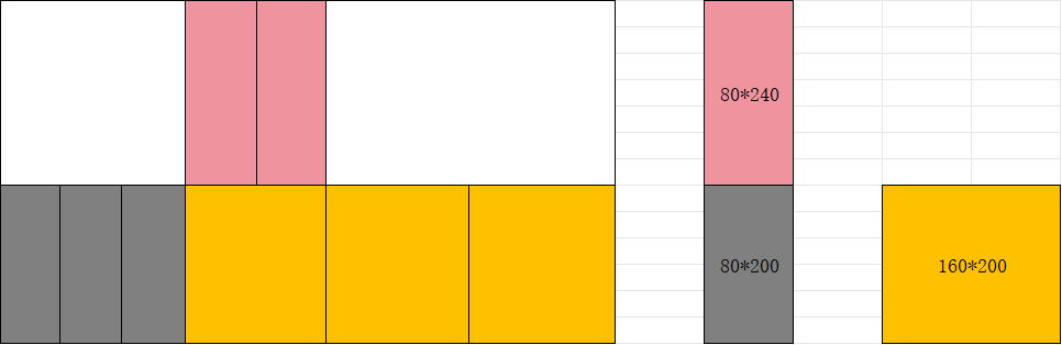
Complex screen connection example
In complex screen mode, screen connection requires coordinate settings.
⚠️ Note: Complex Screen Connection is only for devices like the MCTRL series and TB series. If your project is important and large-scale, we recommend choosing the VX PRO series and COEX series.
In the screen connection interface, select the complex screen.
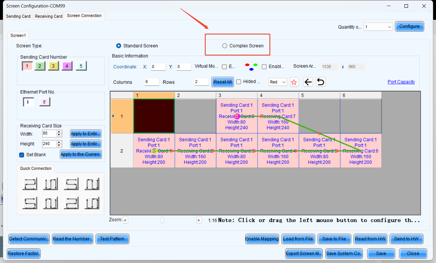
Select complex screen
Since the height of the upper half is 240 pixels, the coordinates of receiving card 1 are (0, 240). Similarly, the coordinates for receiving card 2 should increase by the width of receiving card 1 (80 pixels) along the X-axis. Therefore, the coordinates for receiving card 2 are (80, 240). The coordinate calculation logic for the remaining receiver cards remains the same as that of 1 and 2.
⚠️ Note: Complex Screen Connection still has a rectangular load limit. You can also move blocks with your mouse to align them.
Complex screen coordinate settings
3. Additional features
This document primarily covers the brightness adjustment features of different NovaStar's product line and the configurations across different product series for brightness adjustment.
3.1. Brightness Setting
3.1.1. Manual Adjustment
1. Operation Scenario
Manually adjust screen brightness, Gamma, color temperature, and color gamut to instantly change the brightness and color performance of the display, meeting environmental conditions and user requirements.
2. Operating Procedure
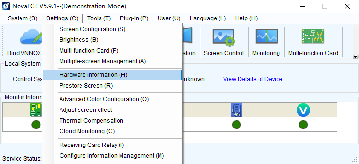
- Step 1: Click or choose Settings > Brightness from the menu bar.
- Step 2: Select Manual Adjustment.
- Step 3: Drag the slider to adjust brightness and select Grayscale or Contrast. You can also set Gamma Interlink if the screen is using receiving cards with TBS6332 or TBS6336 chips.
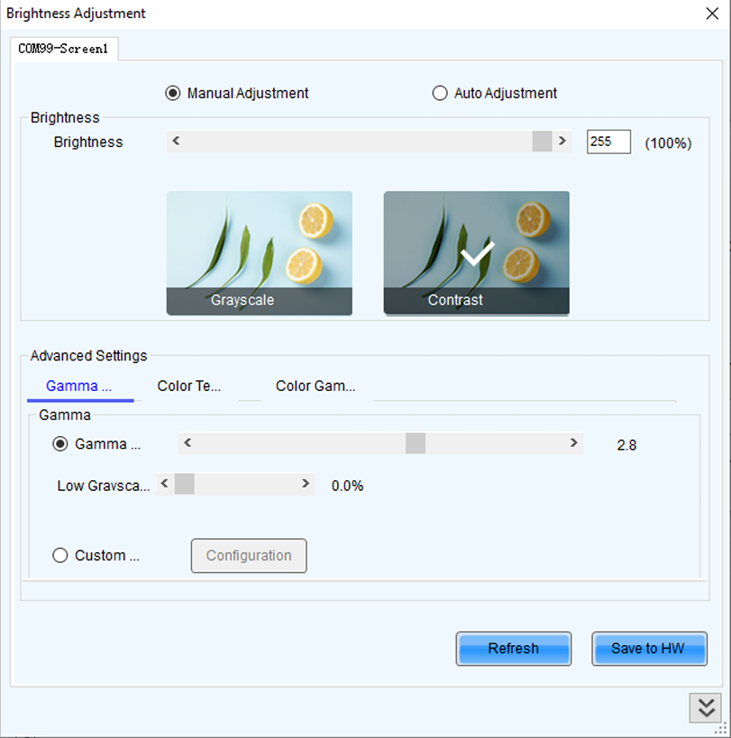
Manual adjustment
- Step 5: After the configuration is done, click Save to HW to save the configuration to the hardware.
3.1.2. Adjust Brightness Automatically
Automatic adjustment requires synchronization between the device time and the real time.
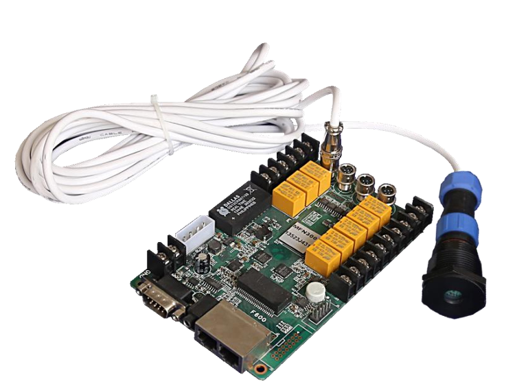
Introduction of the Multi-Function Card and Light Sensor
Multi-Function Card:
- Device Name: MFN300
- The MFN300 is a multifunction card with various functions, such as power switch control, sensor connection, and audio output.
Light Sensor:
- Device Name: NS060
- The NS060 is a light sensor that can be connected to sending cards, asynchronous cards or multi-function cards for ambient brightness monitoring, allowing for automatic brightness adjustment of LED display.
- The sensor body of NS060 is made of aluminum alloy. The sensor surface adopts micro-arc oxidation process, and therefore it is highly UV-resistant and will not be discolored. The joint between the sensor body and the male connector has a very deep groove and is extremely waterproof.
Hardware Connection
Some kinds of the product support connect it to the light sensor directly. Some devices need the multi-function card. This is the figure about connection of hardware.
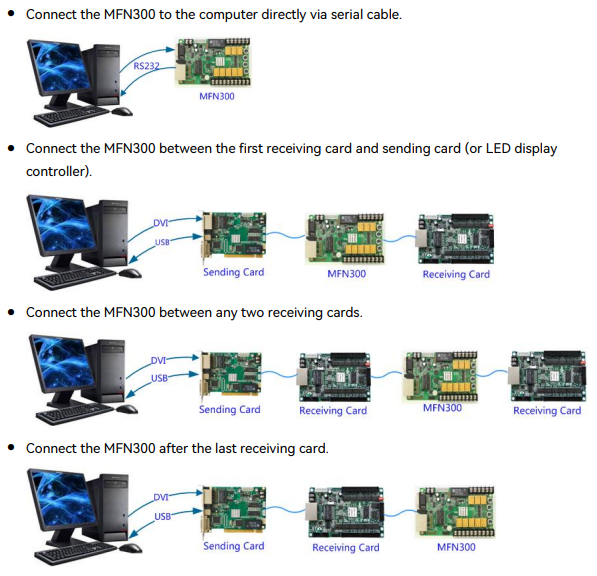
Light sensor direct connection
Light sensor via multi-function card
- Applications: Set rules for automatic brightness adjustment, allowing NovaLCT or sending cards to automatically adjust screen brightness.
- Applicable Products: All sending cards
- Prerequisites: When screen brightness is adjusted based on ambient brightness, a light sensor must be connected to the sending card or multi-function card. If the light sensor is connected to the multi-function card, peripheral configuration needs to be completed on multi-function card management page.
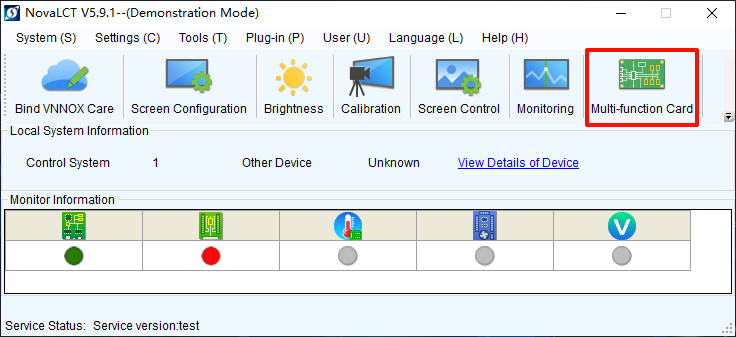
Peripheral configuration
Light sensor monitoring
Related Information
After you configure the automatic brightness adjustment, two adjustment modes are provided.
- Software adjustment mode
- NovaLCT automatically adjusts screen brightness. This mode takes effect when the control PC is connected to the sending card and monitoring is running. The adjustment process will be recorded as a log which can be exported and viewed in iCare of VNNOX cloud platform.
- Hardware adjustment mode
- The sending card automatically adjusts screen brightness. This mode takes effect when the control PC and sending card are disconnected or monitoring stops running.
- Combined screens do not support this mode.
- The adjustment process will not be recorded as a log.
Software adjustment mode
Hardware adjustment mode
Operating Procedure
- Step 1: Click Brightness or choose Settings > Brightness from the menu bar.
- Step 2: Select Auto Adjustment.
- Step 3: Click Wizard Settings. If the auto adjustment table is configured, you can add, delete and modify items in the table, or click Light Sensor Configuration to set light sensor information.
- Step 4: Select an adjustment mode as required and click Next.
Advanced adjustment
Screen brightness is adjusted by time periods. You can choose to adjust screen brightness according to specified brightness or ambient brightness.
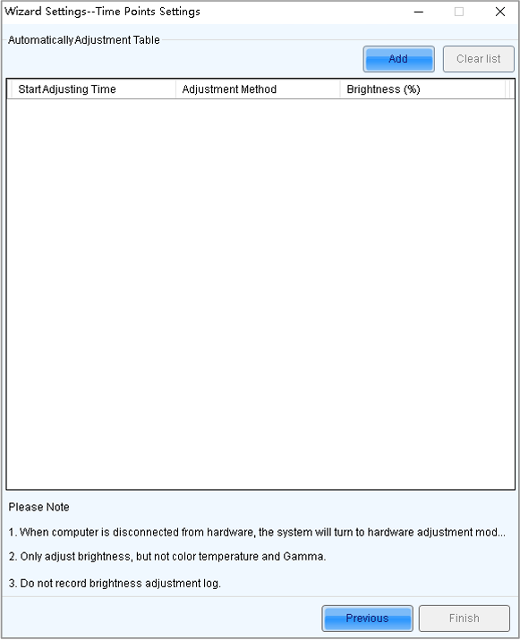
Advanced adjustment
a. Click Add. b. Set the start time and adjustment method and then click OK.
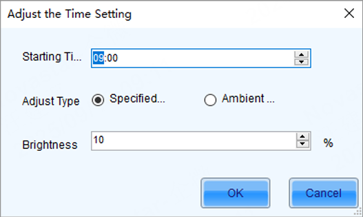
Add adjustment item
c. After the settings are done, click Cancel to close the dialog box. As shown in the figure below, the two configuration items denote that screen brightness will be adjusted to 80% from 8:00 to 18:00 and adjusted to the corresponding values in the brightness mapping table according to ambient brightness from 18:00 to 8:00 of the next day.
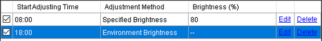
Brightness schedule
d. If there is no Environment Brightness under Adjustment Method, click Finish. If there is Environment Brightness under Adjustment Method, click Next and complete light sensor settings according to the description in Light Sensor Adjustment below.
Light sensor adjustment
Screen brightness is adjusted according to ambient brightness. Set the corresponding relations between ambient brightness and screen brightness in the ambient brightness mapping table.
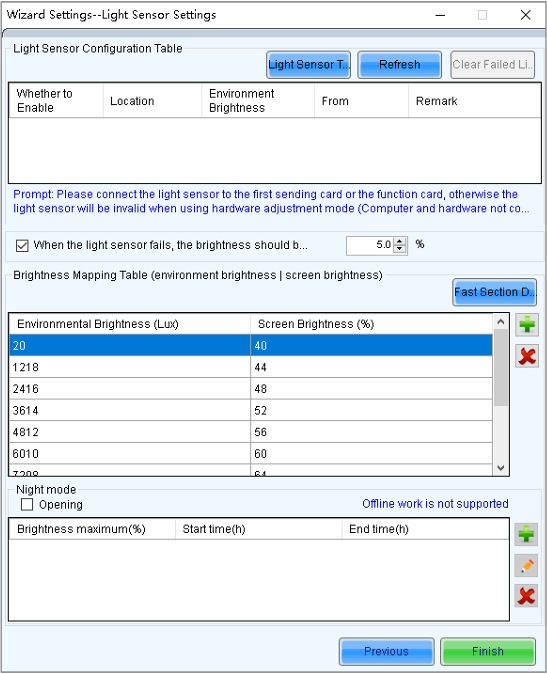
Light sensor adjustment
a. Click Light Sensor Test to test the light sensors connected to the control system, including the light sensors connected to all sending cards and multi-function cards. If you want to clear the ineffective light sensor information, click Clear Failed Light Sensor Information. b. (Optional) Select When the light sensor fails, the brightness should be adjusted to and set a brightness value. If this option is not selected, the screen brightness will keep the last updated brightness value when the light sensor fails. c. Click to add or delete, or click Fast Section Division to set the brightness mapping table. Fast section division can equally divide the ambient brightness range and screen brightness range into the specified number of segments. d. (Optional) Select Opening to enable night mode and set the maximum brightness of the specified time period. When surrounding lights interfere with the light sensor or an exception occurs when the light sensor is collecting ambient brightness data, screen brightness may be too high. This can be avoided in night mode. If the start time and end time are the same, night mode takes effect all the time. e. Click Finish.
- Step 5: After the settings are done, click Save.
- Step 6: (Optional) Click Export Log to export the brightness adjustment log in software adjustment mode.
- Step 7: (Optional) Set the advanced parameters of auto brightness adjustment.
- On the taskbar, click the brightness icon and choose Brightness Advanced Settings.
![]()
Brightness icon
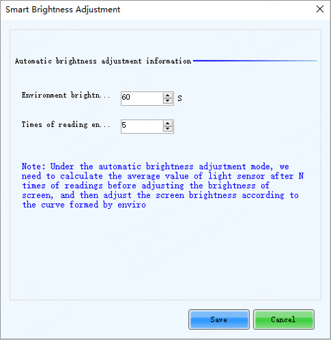
Brightness Advanced Settings
- Set the cycle and number of times for the light sensor to measure ambient brightness. For example, if the cycle is 60 seconds and number of times is 5, the light sensor will measure ambient brightness every 60 seconds. After 5 times of measurement, NovaLCT will calculate the average of the measured values without the maximum and minimum ones. This average value is ambient brightness. If multiple light sensors are connected, NovaLCT will calculate the average of all the ambient brightness values.
- Click Save.
3.2. Notes
- When the product connect to the LCT for brightness adjustment. If the LCT is disconnected, automatic adjustment will become ineffective.
- During screen configuration, ensure that the network port selected in the software corresponds to the actual physical network port; otherwise, brightness adjustment may not take effect.
- The multifunction card can connect to two types of peripherals: a light sensor and a temperature sensor. After connecting, configure them in the peripheral settings module. When a light sensor is connected, select "Light Sensor" for the corresponding peripheral port. When a temperature sensor is connected, select "3D Transmitter" for the corresponding peripheral port (due to historical reasons, this naming has not been modified).
- When multiple light sensors are connected, if software-based automatic brightness adjustment is used for the screen, you can select a specific light sensor as the adjustment reference during configuration (the adjustment will be based on the measured value of the selected light sensor; if multiple light sensors are selected, the average of their measured values will be used for adjustment). If hardware-based offline brightness adjustment is employed, the controller will calculate the average of the measured values from all light sensors connected to the multi-function card before making adjustments.
- The time of the device must be synchronized with real time.
3.3. Frequently Issues And Troubleshooting Methods
1. Question about the light sensor
Q: Can I connect both a light sensor (brightness sensor) and a temperature sensor externally without using a multifunction card?
A: Currently, the TB series board comes with a built-in 485 interface that can only connect to one sensor at a time, such as the NS060, MTH310, or ALP050. Connecting two sensors simultaneously will cause protocol conflicts. If a multifunction card is used, you can connect both the MTH310 and NS060, or the MTH310 and APL050 simultaneously.
2. Common Brightness-Related Issues with All-in-One Devices
Issue Description:
- The device is not set to automatic brightness, but the brightness jumps automatically.
- The large screen displays abnormally after adjusting brightness via the front panel.
Troubleshooting Methods:
For Automatic Brightness Changes:
- Observe the LCT software to see if the brightness automatically jumps to the auto-brightness interface.
- Disconnect all network connections from the computer, switch the brightness mode from auto to manual, and solidify the setting. Observe if it still jumps to auto-brightness.
- a. If it returns to normal after disconnecting, the issue is caused by cloud platform influence. You can delete the corresponding cloud configuration or unbind the device.
- Delete the NovaLCT 2012 configuration file, then observe if the device operates normally to determine if the LCT software is the cause.
- Disconnect the USB connection and observe if the problem persists. If it does, restore the sending device to factory settings and check if it returns to normal.
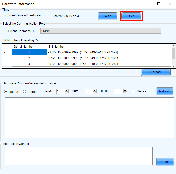
- Use the software to read back the device's SN (Serial Number) and check if it is abnormal (e.g., all 'FF' or '00'). If so, please contact NovaStar technical support for assistance.
3. Common Issues with the NS060 Light Sensor
Q1: In the light sensor specifications only list models with 5-meter and 10-meter cable lengths. How can customers obtain light sensors with cables longer than 10 meters?
A1:
- Currently, our company should still have light sensors with 30-meter and 100-meter cable lengths available for direct purchase.
- Customers can also extend the cable length themselves by purchasing sensor cables with good shielding layers and making their own extensions.
Q2: When using the light sensor for automatic brightness adjustment, the detected ambient brightness is 50000 lux, but the screen brightness does not change. What is the reason?
A2: The light sensor is damaged. According to our supplier, the maximum measurement range of our light sensor is 0~40,000 lux. A reading of 50,000 lux indicates the sensor is damaged.
Q3: Can the light sensor be used underwater or in the rain for extended periods?
A3: The protection rating of our light sensor is IP65. It can withstand short-term use in rain, but prolonged use may lead to water ingress and damage. Additionally, our light sensor cannot be used while submerged in water.
3.4. Backup Setting
3.4.1. Ports Backup
1. Hardware Connections
The signal originates from one sending card, with receiving cards connected to each other via network cables. The last receiving card connects back to the sending card through another network port, forming a loop.
Ports backup hardware connection
2. Setup Steps
Open NovaLCT and login (password: admin), then enter Screen Configuration.
Screen Configuration
- After opening the screen configuration, click the sending card interface. In the redundancy section, click Add, set up the backup, send, and save.
Ports backup setup
⚠️ Note: Device backup and ethernet port backup are mutually exclusive, only one can be configured at a time. Hot backup verification is applicable to MCTRL 4K and MCTRL R5.
3.4.2. Device Backup
Precautions:
- The primary and backup devices must ensure that the models and firmware versions are consistent. When using modularly designed devices, please ensure that the number, slots, models, and firmware versions of the output cards are consistent.
- The configurations of the two devices are identical, with consistent screen connection.
- When setting up a backup, first disconnect the backup device from the receiving cards, then reconnect it after the backup configuration is complete.
1. Hardware Connections
The signal originates from two sending cards, with the receiving cards connected via Ethernet cables, ultimately linking to the backup sending card to form a loop.
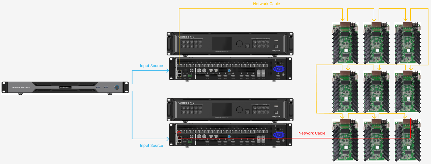
Device backup hardware connection
- The primary and backup devices must ensure that the models and firmware versions are consistent. When using plug-in card devices, it is also necessary to ensure that the number, slots, models, and firmware versions of the output daughter cards are consistent.
- The configurations of the two devices are identical, with same screen connection. Please readback screen connection from the primary device and send to backup device.
2. Setup Steps
Select the corresponding communication port for the primary and backup devices.
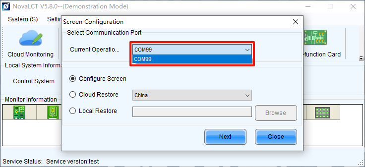
Select communication port
Set the current device as primary or backup.
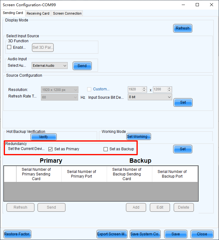
Set primary or backup